


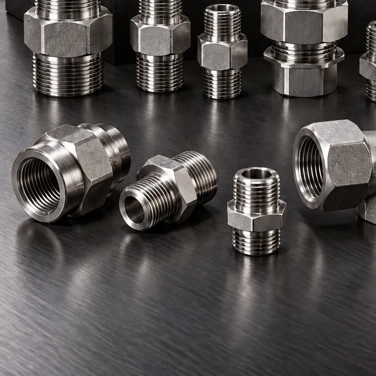
DIN 2353 Compression Fittings
Male Stud Connector (BSPP)
Stainless steel male stud connector with a 24° cone tube end and BSPP male thread, connecting tube to pump, valve block or…
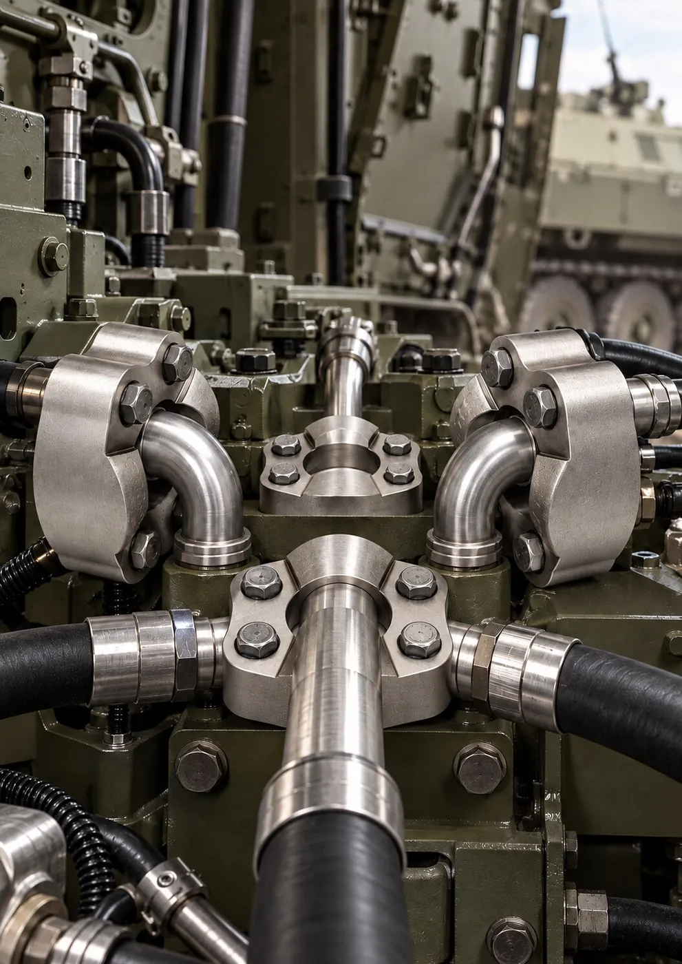
Mobile hydraulics · Technical drawings · Repeatability
SAE flanges, adapters, elbows and hose fittings CNC-machined after technical drawing approval for mobile hydraulic systems, maintenance benches and compact power units.
Featured products in this sector
View all 19 productsProducts
19 products are listed for the operating conditions of Defense Industry. Narrow down by group; open a product page for sizes and thread standards.
DIN 2353 Compression Fittings
Stainless steel male stud connector with a 24° cone tube end and BSPP male thread, connecting tube to pump, valve block or…
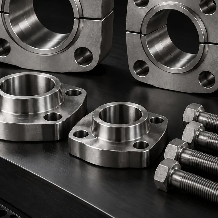
SAE Flanges (Code 61 / 62)
Two-piece stainless steel split flange clamp that holds a flanged-head hose fitting or tube end against an SAE Code 61 port…
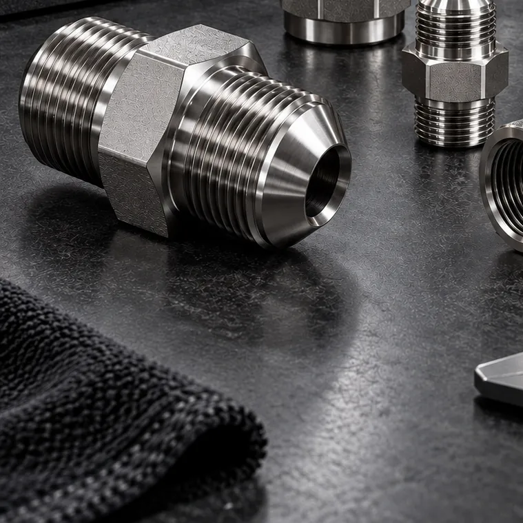
JIC 37° Fittings & Adapters
Stainless steel straight adapter with UNF male threads and JIC 37° cone seats at both ends. Joins two female swivel hose or tube…
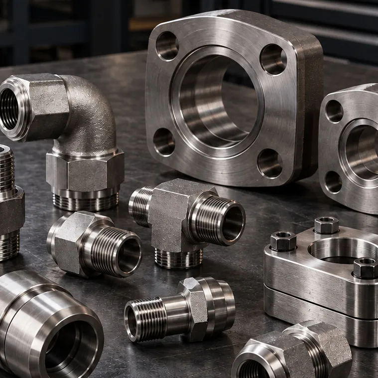
SAE Flanges (Code 61 / 62)
Stainless steel flange block combining SAE flange ports in a single body with elbow, spacer, reducer or distribution functions…
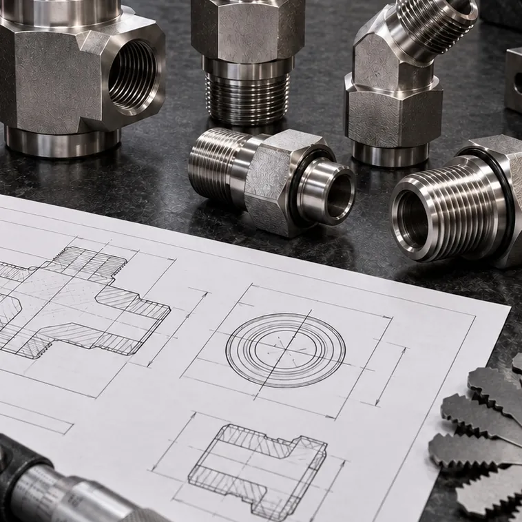
Custom-Made Hydraulic Parts
Custom stainless hydraulic adapter CNC-machined from a sample or technical drawing for thread, size and angle combinations not…
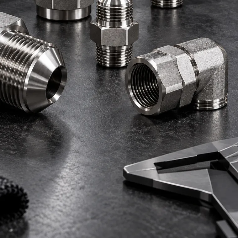
DIN 2353 Compression Fittings
Stainless steel 24° cone equal elbow providing a weld-free 90° change of direction in a tube line. For tight installation spaces…
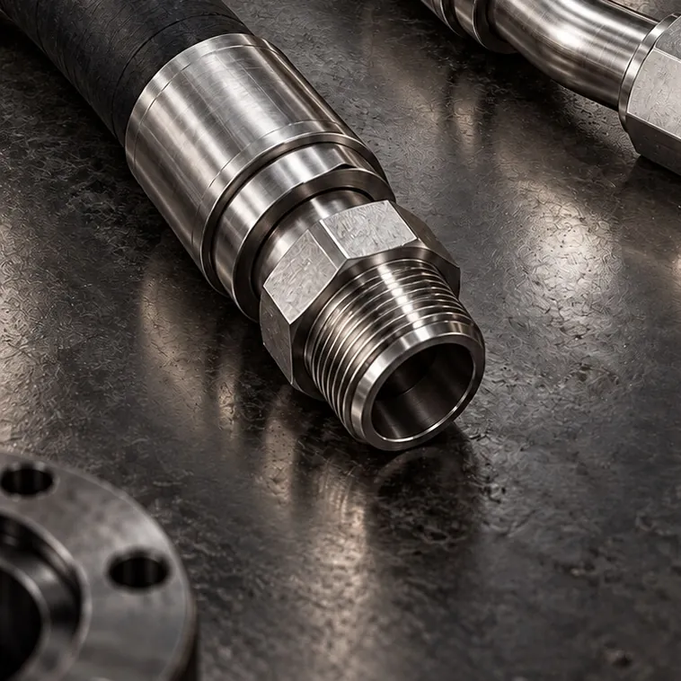
Hose Fittings & Ferrules
Stainless steel straight hose fitting with a female UNF swivel nut and JIC 37° cone seat. Crimp hose end for hydraulic systems…
Hose Fittings & Ferrules
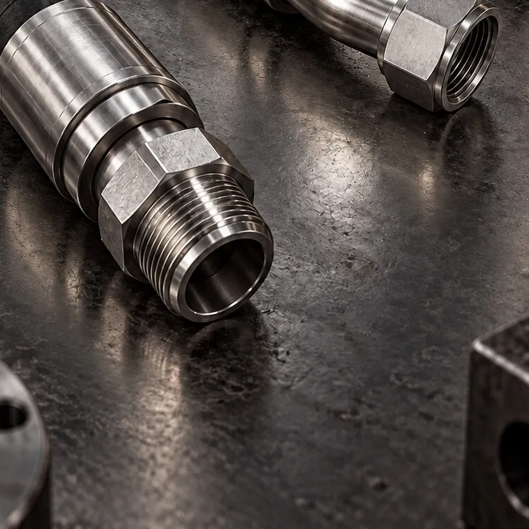
Stainless steel O-ring face seal (ORFS) hose fitting with a female swivel nut. Reduces the risk of leaks in high-pressure lines…
Hose Fittings & Ferrules
Stainless steel ring-type (banjo) hose fitting connected to the port with a hollow bolt. Rotatable connection perpendicular to…
SAE Flanges (Code 61 / 62)
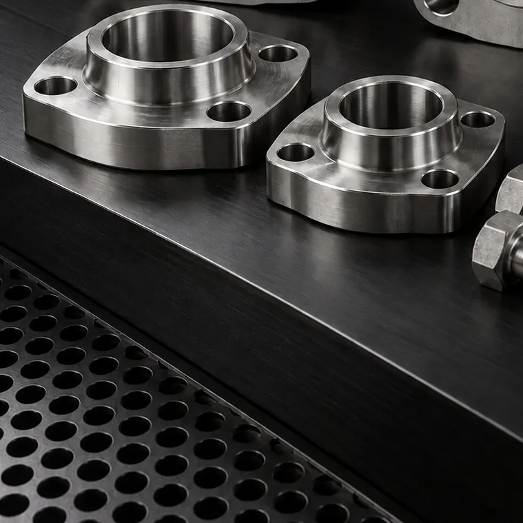
Stainless steel SAE Code 62 mating flange for high-pressure hydraulic lines. Connects the pipe to a Code 62 port via a welded or…
Ball, Needle & Check Valves
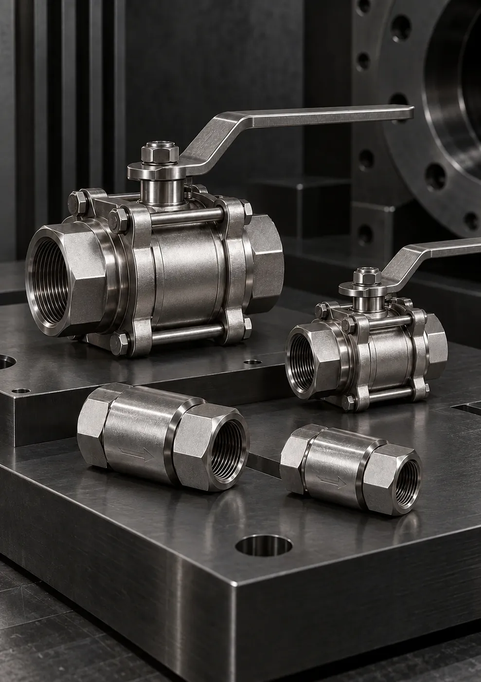
Stainless steel needle valve with a tapered stem for fine flow adjustment and isolation of measurement lines. For gauge, sampling…
Twin Ferrule Instrumentation Fittings
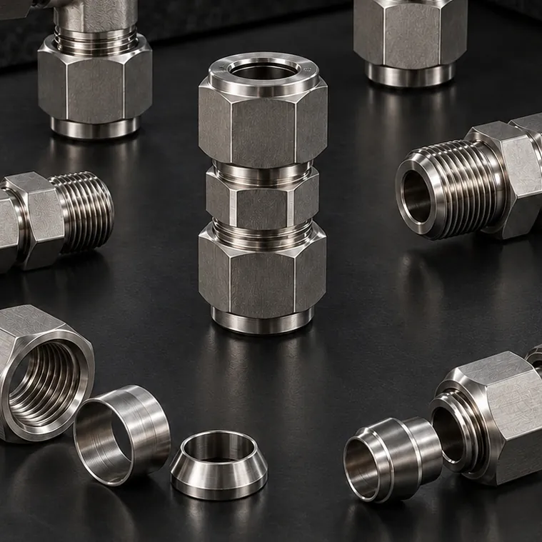
Stainless steel twin ferrule male connector joining instrumentation tube to a threaded port, with a tube end on one side and a…
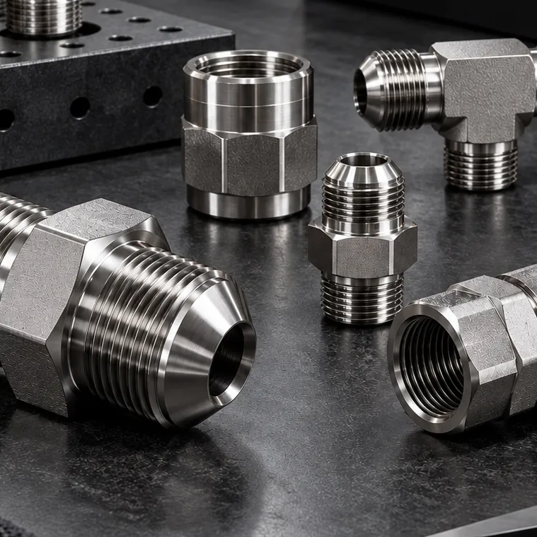
JIC 37° Fittings & Adapters
Straight stainless steel adapter with a JIC 37° UNF male end and an NPT tapered male thread. Connects JIC hoses or tubing to…
JIC 37° Fittings & Adapters
Stainless steel conversion adapter with a JIC 37° UNF male end and a BSPP parallel male thread. For connecting JIC hose lines to…
JIC 37° Fittings & Adapters
Stainless steel 90° elbow with a JIC 37° male end and a JIC 37° female swivel nut end. Routes hoses without twisting and makes…
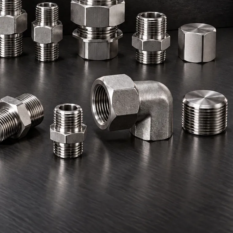
JIC 37° Fittings & Adapters
Male plug for sealing JIC 37° female ends and female cap for sealing male ends. Stainless steel, for sealing off lines, pressure…
JIC 37° Fittings & Adapters
Straight stainless steel ORB to JIC adapter with an SAE O-ring boss (UNF) port end and a JIC 37° male line end. Secure port…
Quick Disconnect Couplings
Stainless steel-bodied male-female quick disconnect coupling with BSP threads. Fast, tool-free connection at test points, on…
Custom-Made Hydraulic Parts
Stainless steel manifold blocks machined from solid to technical drawings, combining multiple hydraulic lines in a single body…
Can't find your part in the list?
Send a sample photo, technical drawing or dimensions; we'll identify the right fitting from our catalog or through custom manufacturing.
Faik Güney · Contact person
Services
Beyond supplying parts, we complete the job in the field with piping, hose assembly, custom manufacturing and technical identification.
Thread profiles, sealing cones, wrench flats and connection geometry are machined from AISI 316/316L bar on CNC…
View service – Stainless Steel CNC MachiningWhere a standard product is not the answer: custom adapters, nipples, flange blocks and transition parts made from a…
View service – Custom Parts from Drawings & SamplesOrderly, labeled and service-friendly connections with stainless steel tube and fittings on control panels, power units…
View service – Control Panel & HPU TubingHydraulic hose assembly and crimping: hose assemblies with straight, 45° and 90° stainless steel ends in BSP, JIC, NPT…
View service – Hydraulic Hose AssembliesIdentifying BSP, NPT, UNF/JIC and metric threads by measurement, matching them correctly to the mating part, and…
View service – Fitting & Thread IdentificationStainless steel hydraulic fittings and hose assemblies for ship and boat steering systems and for passerelle, crane and…
View service – Steering Gear & Actuator PartsAISI 316/316L tube with twin-ferrule union, elbow, tee, connector and adapter fittings for small-bore measurement…
View service – Instrumentation TubingOverview
Quick answer
In the defense industry, SAE Code 61/62 flanges, adapters, elbows and hose fittings are used in mobile hydraulic systems, maintenance and test benches, and compact power units. Selection is based on working pressure, vibration, installation space and connection orientation. Parts are CNC-machined after technical drawing approval and produced with the same dimensional inspection routine throughout the series.
In defense projects, a fitting is expected to do more than simply not leak. The same part must arrive in the same dimensions in the first series and in later batches, the tolerance on the technical drawing must be held in every batch, and it must be known which raw material batch the part was made from. In mobile hydraulic systems, maintenance benches and compact power units, dimensional repeatability and secure connections come first.
GÜNEYSS manufactures the AISI 316/316L stainless steel SAE flanges, adapters, elbows, hose fittings and custom transition fittings needed in defense industry projects to technical drawings. Production starts after technical drawing approval and continues with first article approval and dimensional inspection in every batch.
Field conditions
We select fittings for these conditions and specify the material, sealing type and installation method accordingly.
Describe your own conditionsSpare parts fitted in the field without re-measuring must arrive with the same geometry in every batch.
Mobile systems operating in rough terrain put constant stress on connections; the support arrangement and connection type must be selected together.
In power units and in-vehicle lines, elbow angles, wrench flats and assembly sequence are planned within very tight tolerances.
While a platform stays in service for years, the original fitting supplier may change; reproduction from samples becomes necessary.
A part's history is expected to be traceable from the raw material batch through to shipment.
Technical selection notes
Points we clarify with you before ordering for Defense Industry applications.
The current revision of the technical drawing and the critical dimensions are confirmed in writing before production.
Series production begins after dimensional inspection and approval of the first part.
In circuits with transient pressure peaks, flange class and fitting type should not be selected on nominal pressure alone.
Whether the equipment is of European or US origin determines the choice of metric, BSP, JIC/UNF or SAE.
When documentation, testing and confidentiality requirements are specified at the quotation stage, the production plan is set up accordingly.
Detailed guide
In defense projects, the part definition usually comes with the customer's technical drawing. Before production, material grade, connection standard, critical tolerances and surface requirements are confirmed; no dimension that remains unclear is released to production.
At raw material receiving, surface, diameter and batch information are checked; a traceable batch system makes it possible to track which raw material batch a part was made from. Any additional documentation, testing or inspection requirements should be stated in writing at the quotation stage. When the technical drawing is revised, the batch from which the change applies should also be clarified in writing; two different revisions of the same part number can cause confusion in the field.
In mobile systems, spare parts are often fitted in the field without re-measuring. If the length or sealing cone of an adapter in one batch differs from the previous batch, the hose route changes, assembly is forced and a leak risk arises. CNC machining makes it possible to produce the same geometry throughout a series with the same program and fixturing; dimensional inspection verifies that repeatability in every batch.
The standard used often depends on the origin of the equipment: European systems more commonly use metric 24° cone bite-type fittings and BSP ports, while US systems more often use JIC/UNF and SAE flanges. The main criteria considered in selection:
| Criterion | What it determines |
|---|---|
| Working pressure and pressure spikes | Code 61 or Code 62 for SAE flanges, fitting body type |
| Vibration and shock | Choice of hose or tube, support and clamp arrangement |
| Installation space | Elbow angle, wrench flats, block connection design |
| Connection orientation | Choice of adjustable elbow or fixed-angle part |
| Environment | Preference for 316/316L stainless steel in salty, dusty or humid environments |
In mobile systems operating under vibration and shock, the way a connection is supported matters as much as the connection itself. Long tube runs should be clamped at suitable intervals, hoses rather than tubes should be used between sections that move relative to each other, and points where a hose rubs against the body should be protected. Overtightening fittings is as problematic as leaving them loose; the sealing surface can be damaged.
In power units installed inside a vehicle or a confined cabinet, standard elbows and adapters often do not fit. In such cases, custom transition fittings that combine two connections in a single piece, adapters with an outlet at a different angle, or blocks with SAE flange connections are designed. Production becomes more predictable when port size, connection orientation and installation clearance are defined on the same technical drawing. The assembly sequence should also be planned: if a connection can no longer be reached with a wrench once the adjacent part has been installed, this should be noted on the drawing or the part geometry adjusted accordingly. Fewer parts also mean fewer potential leak points.
Defense systems remain in service for many years; during that time, the original supplier of some fittings may change or a part may be discontinued. Reproduction from samples or technical drawings ensures spare parts continuity throughout the platform's service life. Planning spare sets for adapters that are frequently removed and refitted on maintenance benches keeps the test schedule on track.
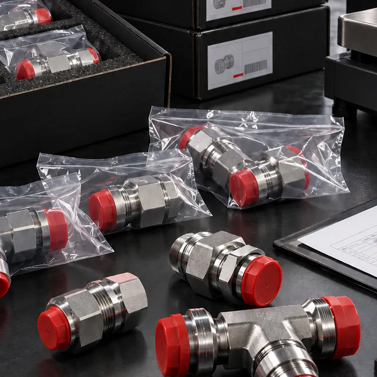
After technical drawing approval, custom-size and project manufacturing is scheduled within 10-20 business days on average. Standard catalog products are prepared within 1-3 business days depending on stock availability, and standard production items within 5-10 business days. Parts are packed separately by size and order group, with protective caps on threads and ports. Please state your drawing sharing and confidentiality requirements at the quotation stage.
Applications
Teams in Defense Industry that need fittings, hose assemblies and custom parts.
Cylinder and line connections for vehicle-mounted lifting, ramp, hatch and outrigger systems.
Custom-angle elbows, block connections and SAE flanges in space-constrained pump and valve block assemblies.
Adapter sets for component test benches; spares planning for frequently removed parts.
Stainless steel adapters, nipples and transition fittings series-produced to technical drawings.
316L fittings for deck and engine room hydraulics operating in salt-laden environments.
Hose and tube connections for hydraulic lifting and handling equipment used in the field.
Gallery
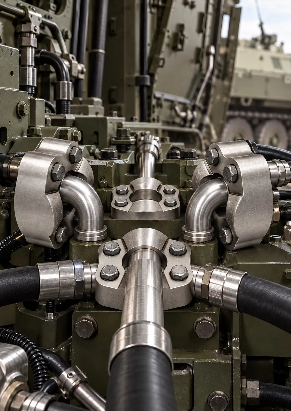
Military vehicle hydraulics and stainless steel connection points (illustrative image)
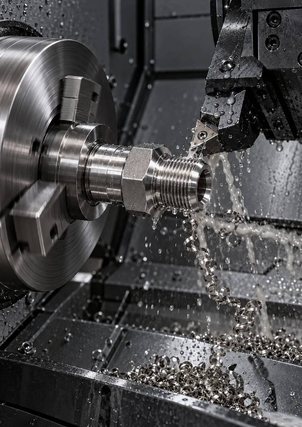 Machining a threaded fitting on a lathe (illustrative image)
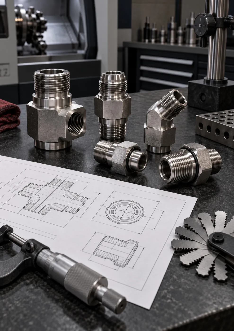 Technical drawing, sample fittings and dimensional inspection with a micrometer (illustrative image)
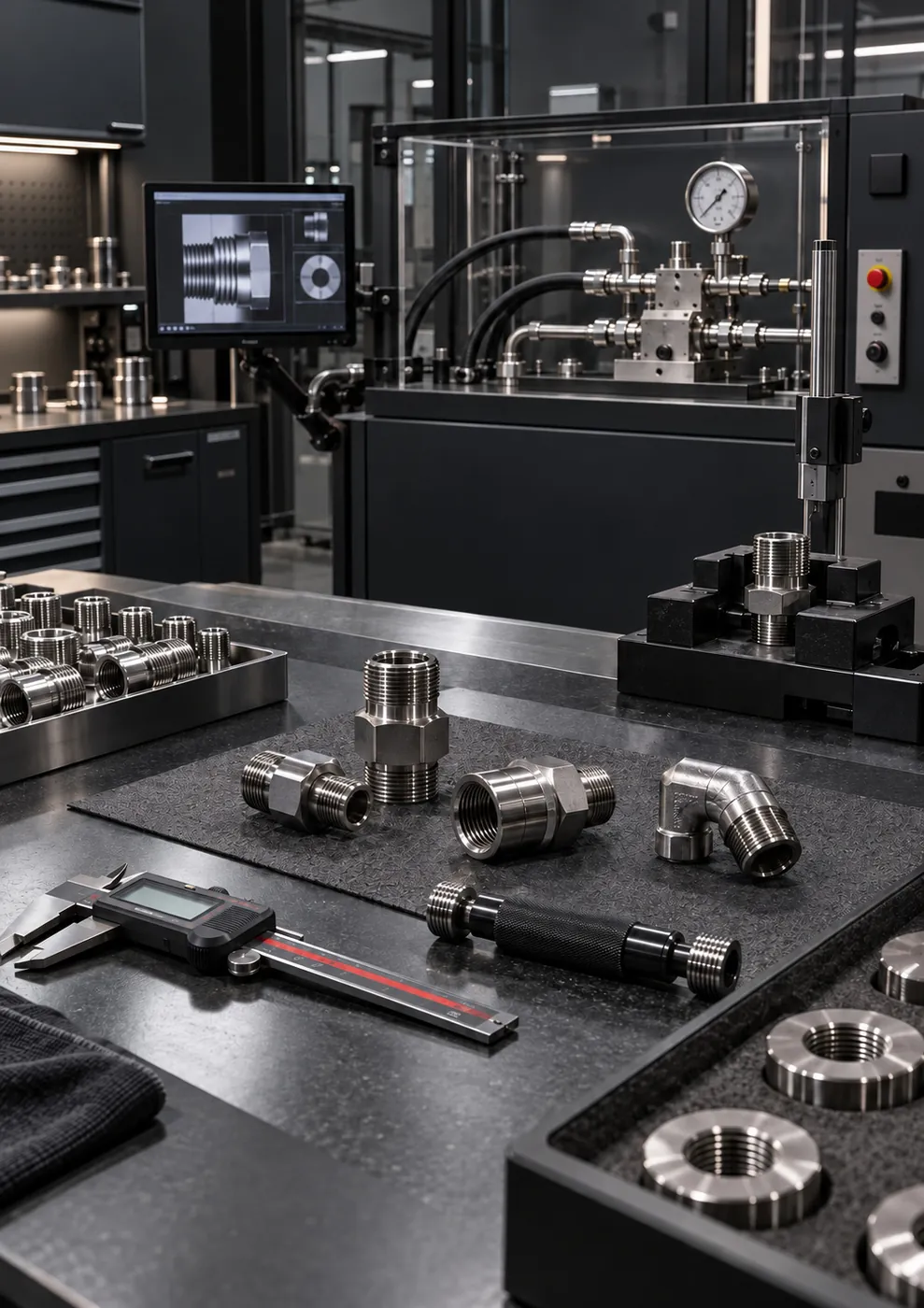 Control and test bench with pressure gauges (illustrative image)
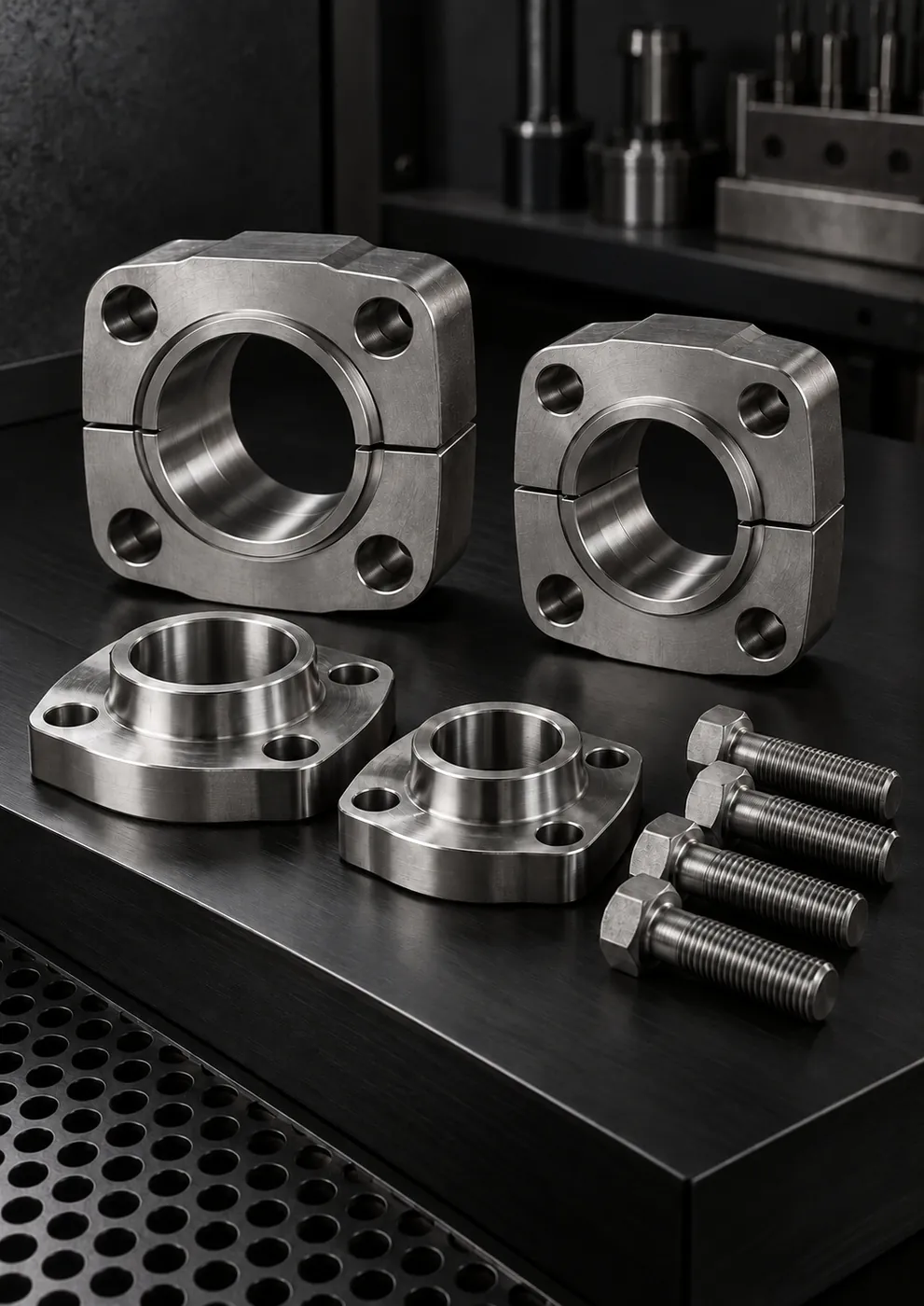 SAE Code 61/62 flanges and bolts (illustrative image)
Knowledge Center
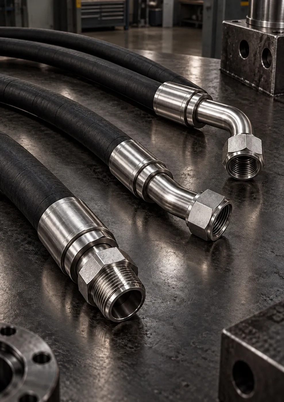
The right hose assembly is defined by seven pieces of information: inside diameter and length, temperature, application conditions, fluid, working…
Code 61 (ISO 6162-1) and Code 62 (ISO 6162-2) flanges are not interchangeable, even at the same nominal size: the Code 62 flange head is thicker and…
When a standard part won't fit, custom manufacturing starts with a sample, a dimensioned technical drawing or dimensional data. The thread standard…
Frequently asked questions
If your question isn't answered here, write to us and we'll pin down the size, thread standard and material together.
Send us your questionYes. Material, thread standard, critical tolerances and surface requirements are confirmed in writing before production. The first part goes through dimensional inspection and is submitted for approval; after this approval, series production is carried out with the same machining and inspection routine.
Parts are machined on CNC machines with the same program and fixturing, and thread fit, diameter, surface and sealing area are checked in every batch. Because batch information is recorded at raw material receiving, it is possible to trace which raw material batch a part was made from.
The technical drawing is used as the common reference for manufacturing and inspection. If your project has drawing sharing and confidentiality requirements, simply state them at the quotation stage; the working arrangement is then agreed together in line with those requirements.
The thread standard, critical diameters and sealing type are determined from a sample or dimensioned drawing; if the dimensions of the mating part are also known, the match can be established more reliably. Custom-size manufacturing is scheduled within 10-20 business days on average after technical approval.
Code 61 is the standard pressure series and Code 62 the high-pressure series; in general classification they are referred to as 3000 PSI and 6000 PSI. Since the permissible pressure varies with flange size, the selection should be made by evaluating nominal size, working pressure and port geometry together. The two series have different flange and bolt dimensions at the same nominal size and are not interchangeable.
Dimensional, thread and surface inspection are part of the standard production flow; pressure and leak-tightness verification is performed depending on the application. If you state your additional testing, inspection or documentation requirements in writing at the quotation stage, whether they can be met and how they affect the lead time will be clarified upfront.
Quote
Share the material, quantity, critical tolerances and any additional documentation requirements; we'll outline the first article approval and series production plan, with lead times.
Defense Industry request form