Shipyards & Ship Repair · Technical guide
Custom Stainless Parts Made to Drawing: The Step-by-Step Process
Quick answer
When a standard part won't fit, custom manufacturing starts with a sample, a dimensioned technical drawing or dimensional data. The thread standard, sealing type and critical dimensions are confirmed in writing before production; for series quantities, series production begins only after the first article has been approved. Custom-size and project manufacturing is scheduled within an average of 10-20 business days after technical approval.
Not every hydraulic system can be built from catalog parts. An adapter for an older machine that is no longer produced, a conversion piece that joins two different standards, a flange block that has to fit into a tight space, or a spare for equipment sourced from abroad: in these cases, the solution is custom manufacturing from a sample or a technical drawing. In custom manufacturing, what determines both the lead time and the result is the quality of the information gathered at the start of the job.
Which parts are custom-manufactured?
Custom manufacturing usually comes into play for parts that resemble standard products but differ in size, thread combination or length:
- Adapters and conversion pieces that join two different thread standards
- Nipples and bulkhead pieces in non-standard lengths or diameters
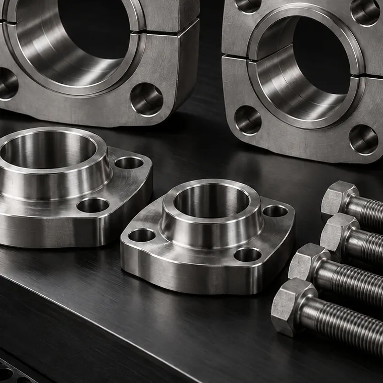
- Flange blocks designed around a tight installation space
- Replacement fittings for equipment that is out of production or increasingly hard to source
Manufacturing inputs
A custom part requires five basic pieces of information. If any one of them is missing, it has to be completed before production starts.
| Input | Why is it needed? | If it is missing |
|---|---|---|
| Sample or dimensioned technical drawing | The single reference for geometry and critical dimensions | Dimensions are filled in by estimate, creating a risk of misfit at installation |
| Material | Corrosion resistance, strength and weldability | A material unsuited to the environment fails prematurely |
| Quantity | Raw material, fixturing setup and production planning | Lead time and cost cannot be calculated accurately |
| Operating conditions | Verifying wall thickness, thread and sealing type against pressure, temperature and fluid | The part fits dimensionally but is overstressed in the field |
| Mating part information | Matching the thread standard and sealing surface | Thread or cone mismatch |
Working from a sample
A sample is the strongest starting point for parts that have no drawing; however, a used part may have worn dimensions, damaged threads or a damaged sealing surface. When sending a sample:
- State where the part connects and which surfaces are functional (thread, cone, O-ring groove, wrench flats).
- If possible, also share the mating part or the port information.
- Note any worn or damaged areas; these areas are redefined to their original dimensions.
- If you cannot send a sample, send clear photos of the part taken from different angles, with a caliper or ruler placed alongside it.
What should a good technical drawing include?
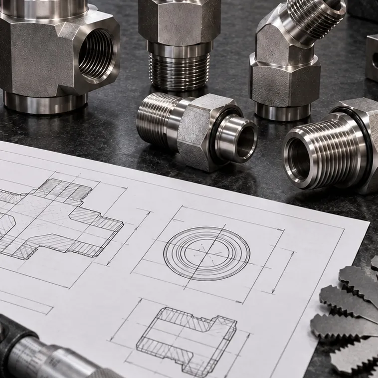
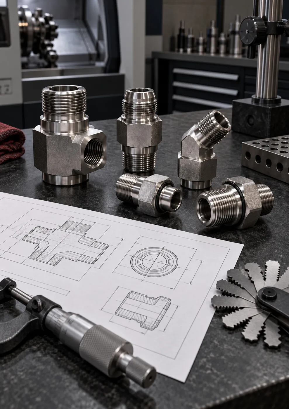
The technical drawing is the common reference for both manufacturing and inspection. The drawing should clearly include the following information:
- Complete thread designation: Instead of "1/2 thread", a standard designation such as G 1/2, 1/2-14 NPT, 9/16-18 UNF or M18x1.5; the thread length and, if applicable, the thread undercut.
- Sealing geometry: Cone angle (24°, 37°, 60°), O-ring groove dimensions and seal seat diameter.
- Critical dimensions and tolerances: Diameters, lengths and center distances that affect assembly, together with their tolerances; a general tolerance note for all other dimensions (e.g. ISO 2768-m).
- Surface finish: The required roughness value, especially on sealing surfaces.
- Wrench flats: Hex or square size; if the part is installed in a tight space, the maximum permissible outside dimension.
- Material and additional requirements: A material designation such as AISI 316L; any marking, testing, cleaning and documentation requirements.
- Revision information: Which version of the drawing it is; changes should be submitted under a new revision number.
Sharing a 3D model, if one is available, speeds up the job. However, since most models do not carry tolerance and thread information, these details must be written on the 2D drawing or in the notes.
Common gaps
- Unit ambiguity: A drawing made for inch-based equipment with some dimensions in millimeters and others in inches. The drawing's unit of measure must be stated clearly.
- Outdated revision: The part in use in the field and the drawing on hand belong to different revisions. If in doubt, compare against a sample.
- Undefined sealing surface: The thread is specified but the cone angle or O-ring groove is left blank.
- Critical dimension without a tolerance: A diameter that has to fit into a mating part is given only as a nominal value.
These gaps turn into questions during the technical review; a drawing that is complete from the outset shortens the verification process.
Written confirmation: speaking the same language before production
Once the inputs are collected, a technical review is carried out: Can the part be produced with the available raw material and machine setup? Are the given dimensions consistent with one another? Are the thread and sealing type suitable for the operating conditions? The thread standard, sealing type and critical dimensions are then confirmed in writing before production. This confirmation can be an approval marked up on the customer's drawing or a dimensioned drawing prepared by us.
The lead time for custom manufacturing starts with this technical approval and averages 10-20 business days. Dimensional changes made after approval can restart the schedule, which is why getting input from everyone involved before approval, especially the team that will carry out the installation in the field, saves time.
First article approval and series production
After technical approval, the drilling, wrench flat, threading and surface operations are planned around the part's fixturing and inspection setup. Critical features such as the sealing surface and threads are machined in a sequence that allows dimensional inspection to be carried out reliably.
For series orders, the first article is produced first and goes through dimensional inspection. Thread fit is checked with thread gauges, critical diameters with measuring instruments, and the sealing surface visually and, where necessary, by measurement. For critical applications, the first article can be submitted for customer approval so that it can be test-fitted to the mating part. Once the first article is approved, series production begins; dimensions are checked at set intervals throughout the run to monitor repeatability.
At the end of production, the parts are deburred and the threads and sealing surfaces receive a final inspection; threads and ports are closed off with protective caps and the parts are packaged by size and order batch. When a repeat order for the same part references the approved drawing and revision number, technical verification takes far less time.
The process at a glance
- Request: sample, technical drawing or photo; quantity and operating conditions
- Technical review and manufacturability check
- Written confirmation of thread standard, sealing type and critical dimensions
- Raw material preparation, cutting and CNC machining
- First article dimensional inspection and, if required, customer approval
- Series production, cleaning and final inspection
- Packaging with protective caps and shipping
Checklist
- Is a sample or a dimensioned technical drawing ready?
- Are the thread designations written in standard notation?
- Are the critical dimensions and tolerances marked?
- Are the material, quantity and required delivery date known?
- Is information on working pressure, temperature and fluid available?
- Have any testing, cleaning, marking or documentation requirements been specified?