


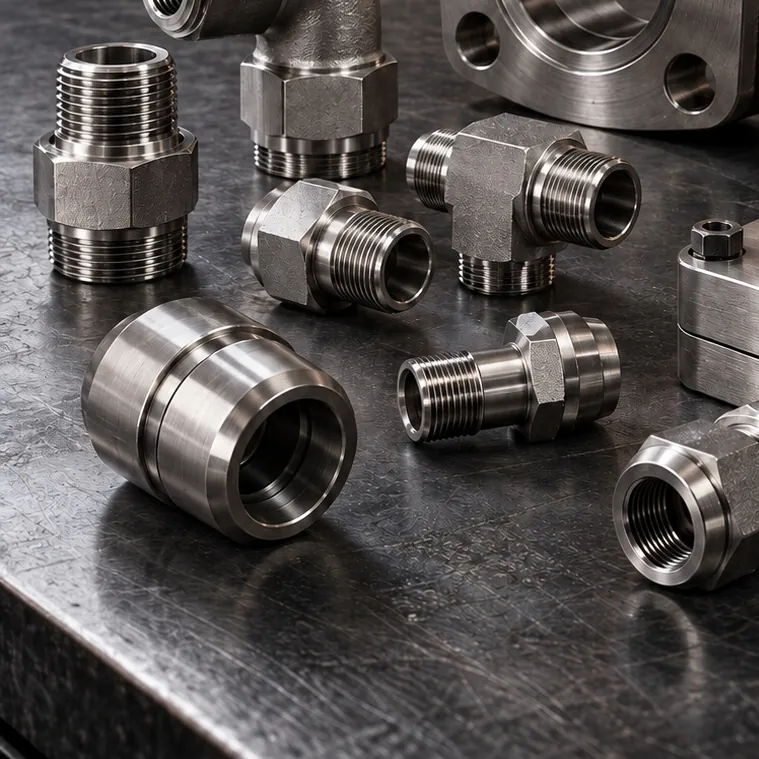
 DIN 2353 Compression Fittings
Equal Tee (24° Cone)
Details & quote
Panel tubing · Pressure gauges · Valve groups
Orderly, labeled and service-friendly connections with stainless steel tube and fittings on control panels, power units and test benches: gauge and test point connections, valve groups and bulkhead penetrations.
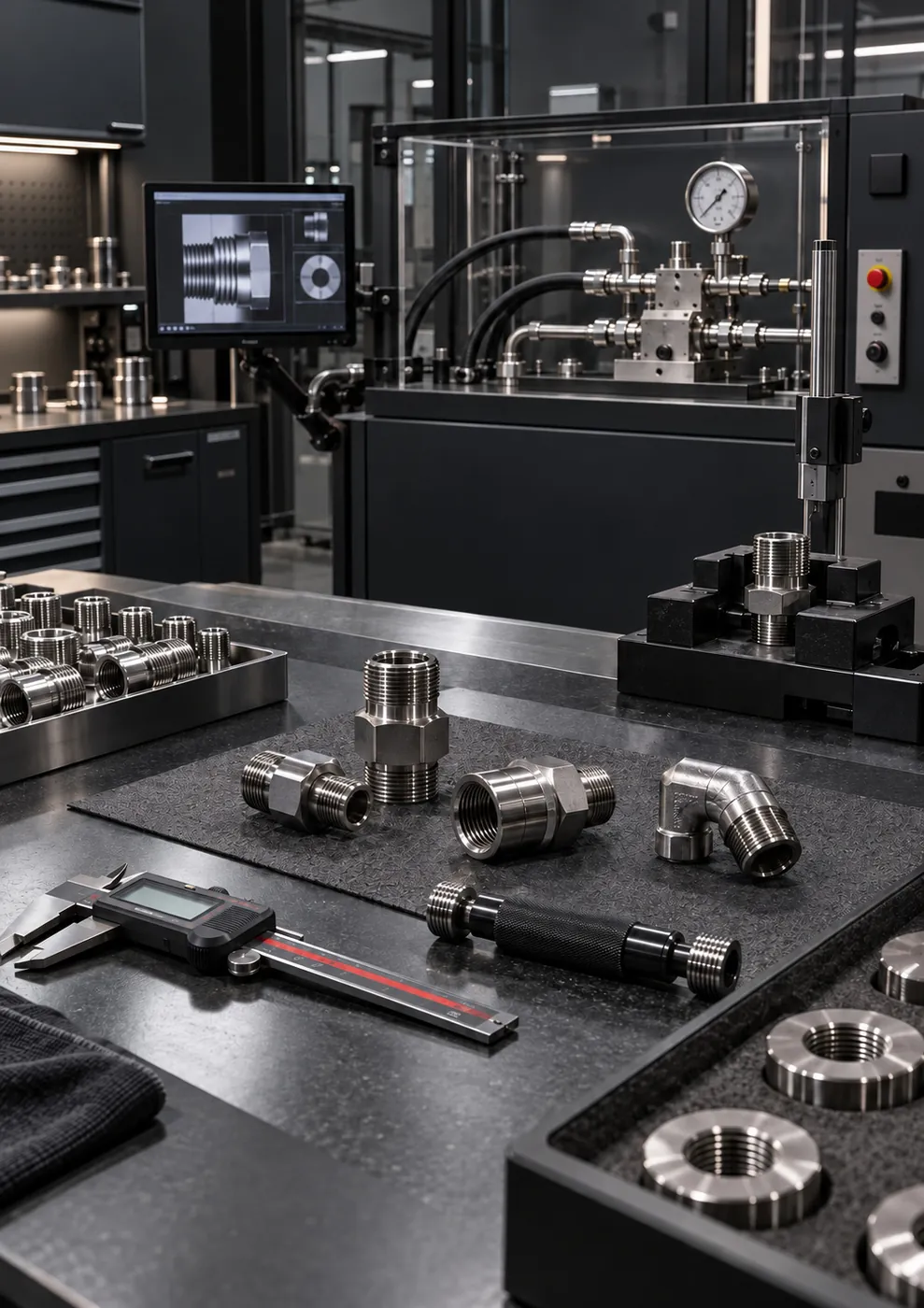
Quick answer
GÜNEYSS selects and prepares stainless steel fittings for hydraulic control panels and power units according to the schematic: instrumentation fittings and tube, pressure gauge and test point connections, valve groups, bulkhead fittings through the panel wall and SAE flange outlets. Panel tubing workmanship is evaluated on a project basis. Hydraulic circuit, electrical and automation design are outside our scope; connections are prepared to the schematic and layout provided by the customer or system designer.
The value of a hydraulic control panel in the field is measured by how quickly it can be read and how easily it can be worked on when something fails. Haphazardly routed tubing, valves that block each other and gauges with no clear indication of which line they belong to all add to maintenance time. Our goal in panel and power unit tubing is a layout that is leak-tight, orderly and understandable to the service team at first glance.
This service covers the stainless steel mechanical and hydraulic connection side of the panel and power unit. Hydraulic circuit design and the electrical and automation side are the responsibility of the system designer; we work from the hydraulic schematic and layout plan provided.
The diameter, pressure and connection standard of each line are taken from the hydraulic schematic. Valves and gauges that the operator uses frequently are placed on the front face, while components that need only occasional attention go at the back. Lines are run parallel and at right angles wherever possible, and crossovers are kept to a minimum.
Pressure gauges are connected with a needle valve or gauge valve in front of them, so the gauge can be isolated and replaced without shutting down the system. Test points are capped and positioned where they can be reached easily with the measuring instrument's hose. The connection thread of gauges and transmitters (BSP or NPT) is confirmed from the instrument itself; threads of the same size but different standards are never forced together.
Valves are positioned with the flow arrow, handle swing area and service access in mind. A ball valve whose handle hits a neighboring component when open, or a check valve installed in the wrong direction, are common panel mistakes that are only noticed at commissioning.
Tube is cut square and clean and deburred; twin-ferrule fittings are tightened with the correct number of wrench turns. Lines are supported with clamps, and bends and routing are planned so that vibration and thermal expansion do not load the connections.
Bulkhead fittings are used on lines that pass through the panel wall. Because the connection is fixed to the panel body, loads from the external hose or tube are not transferred to the internal tubing, and the external line can be replaced without opening up the panel.
Lines, valves and gauges are labeled to match the numbers on the schematic. The labels let the maintenance team in the field read the schematic directly on the panel.
Control panels and power units for deck equipment on offshore installations and drillships; crane, steering and hatch cover hydraulic control panels on ships and in shipyards; compact power units in the defense industry; hydraulic test benches in aviation; instrumentation panels in chemical plants; pump control skids in fire suppression systems; power unit piping in rolling mills.
Standard fittings, valves and connection components are typically ready to ship within 1-3 business days, depending on stock availability. Project-specific work such as panel tubing is scheduled within an average of 10-20 business days after technical approval of the hydraulic schematic and layout. If no schematic is available yet, a preliminary assessment can be made from photos of the existing panel and a list of lines.
Process
From request to delivery in 5 steps
The hydraulic schematic, panel dimensions and instrument list are obtained.
The diameter, pressure and connection standard of each line are taken off; the bill of materials is confirmed.
The positions of valves, gauges and test points are set for access and readability.
Tube cutting, bending and fitting installation are carried out, and lines are supported.
Leak-tightness is verified, lines and valves are labeled, and open ports are capped.
Sectors
On the sector page, you'll find this service's field-specific applications, recommended products and frequently asked questions.
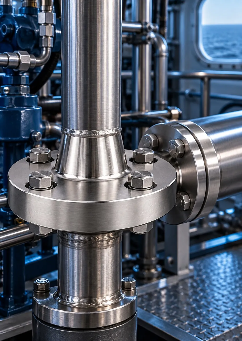
AISI 316L fittings, hose assemblies, SAE flanges and valves built to withstand salt spray and vibration on deck cranes, windlasses, steering gear, passerelles and engine room lines.

Stainless steel pipe, flanges, fittings and hose assemblies, from newbuild piping circuits to drydock overhauls; fast spares from stock for ship crane service teams.

AISI 316L hose ends, SAE flanges, adapters and valves for crane, pipe handling, deck machinery and power unit lines on drillships and platforms.
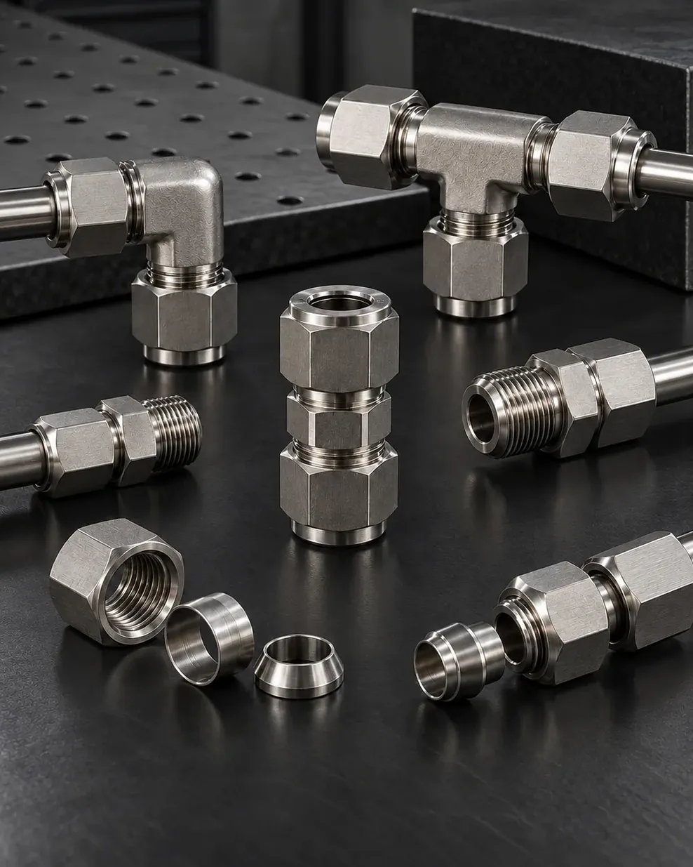
316L twin-ferrule fittings, needle valves, check valves and tubing for wellhead control panels, chemical injection, refinery instrument and sampling lines, and pipeline stations.
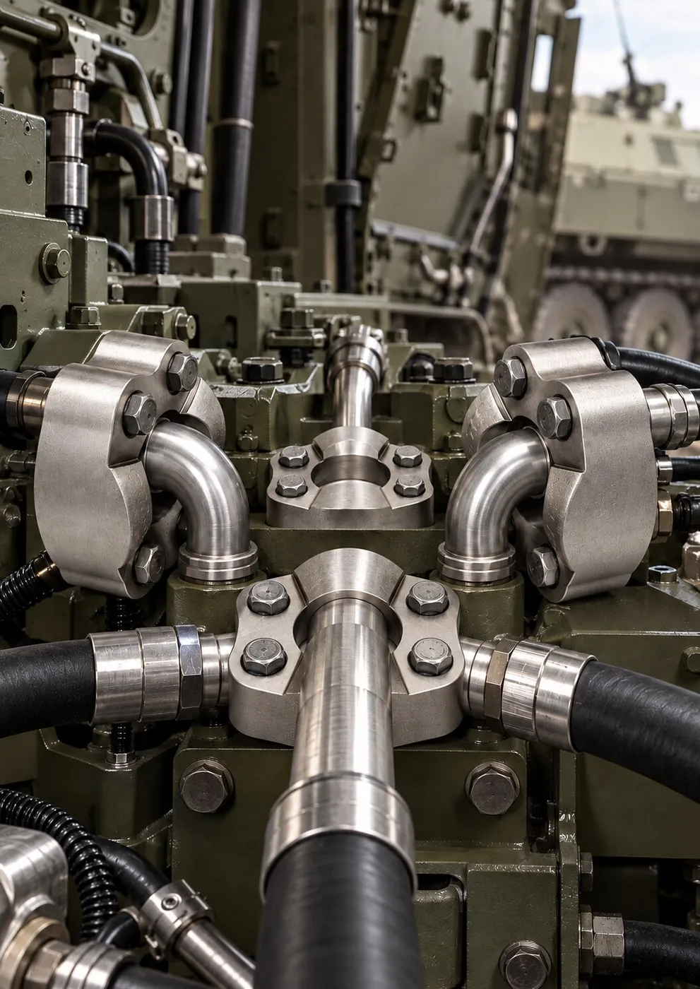
SAE flanges, adapters, elbows and hose fittings CNC-machined after technical drawing approval for mobile hydraulic systems, maintenance benches and compact power units.
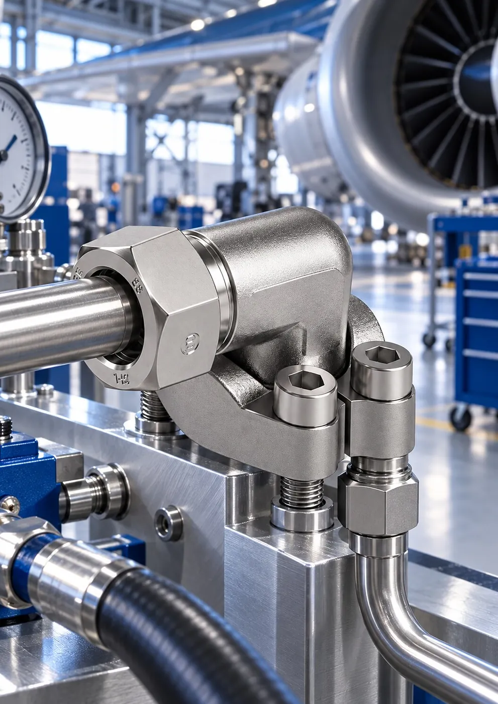
Compact AISI 316/316L fittings with clean threads and sealing surfaces for ground support equipment, hydraulic test benches and maintenance workshops.
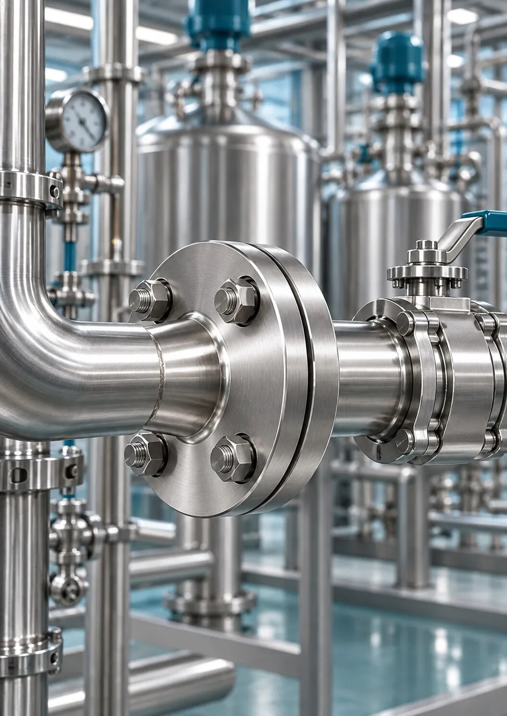
Stainless steel fittings, nipples, valves, flanges and hose fittings for chemical transfer and process lines, selected by weighing fluid compatibility, corrosion resistance, temperature and pressure together.
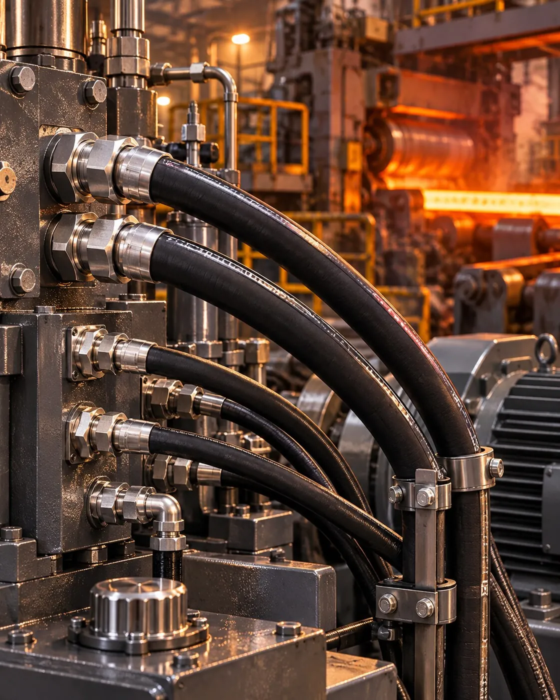
High-pressure hose ends, SAE flanges and adapters built for the high cycling, heat and vibration of presses, mill rolls and hydraulic power units; supplied from stock for emergency maintenance.
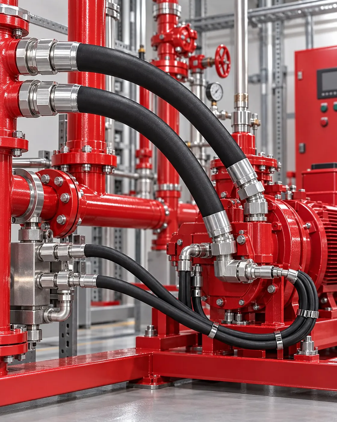
Neatly laid out, leak-tight stainless steel nipples, fittings, hose assemblies and flange connections that make servicing easier on fire pump sets, control skids and pressurized auxiliary lines.
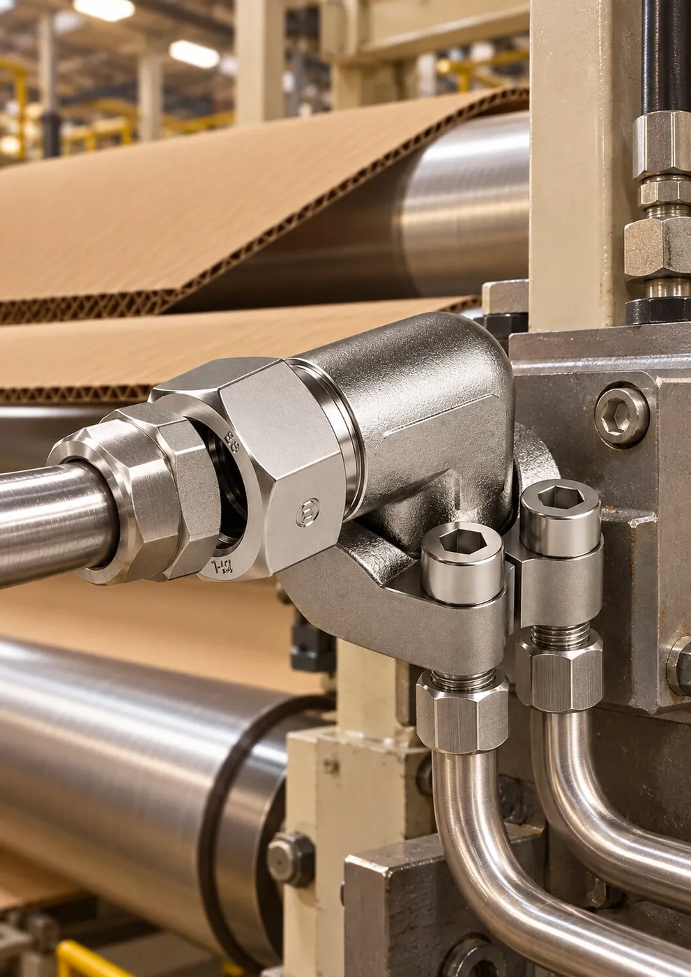
Elbows, tees, adapters, hose fittings and SAE flanges that cut maintenance time for continuously running hydraulic systems on corrugator, roll, cutting and actuator lines.
12 products
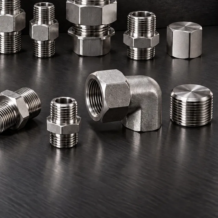
DIN 2353 Compression Fittings DIN 2353 Compression Fittings 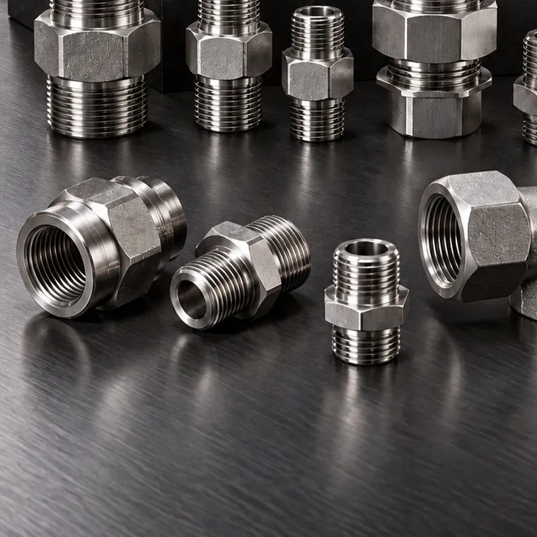 DIN 2353 Compression Fittings
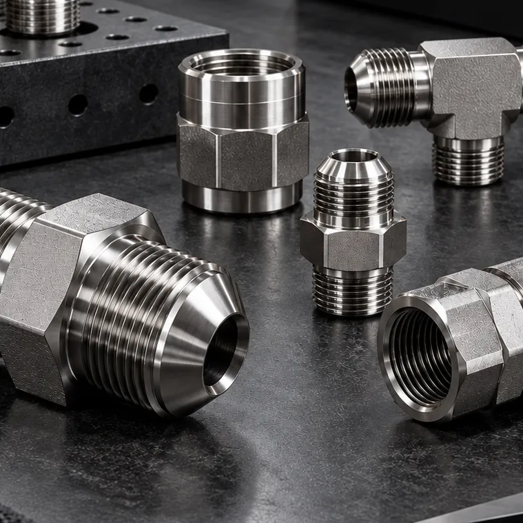 DIN 2353 Compression Fittings
 JIC 37° Fittings & Adapters
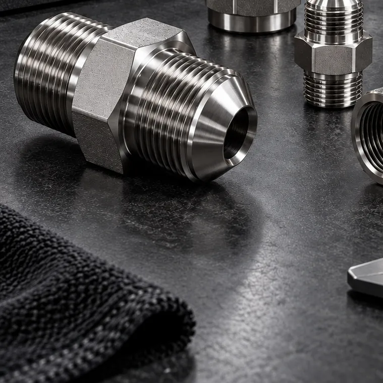 JIC 37° Fittings & Adapters
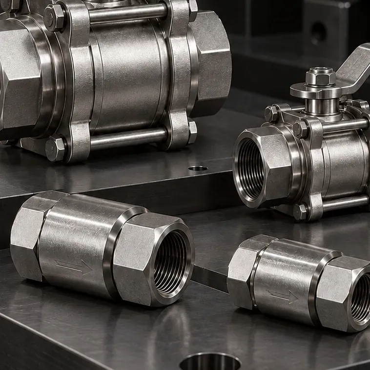 Ball, Needle & Check Valves
 Ball, Needle & Check Valves
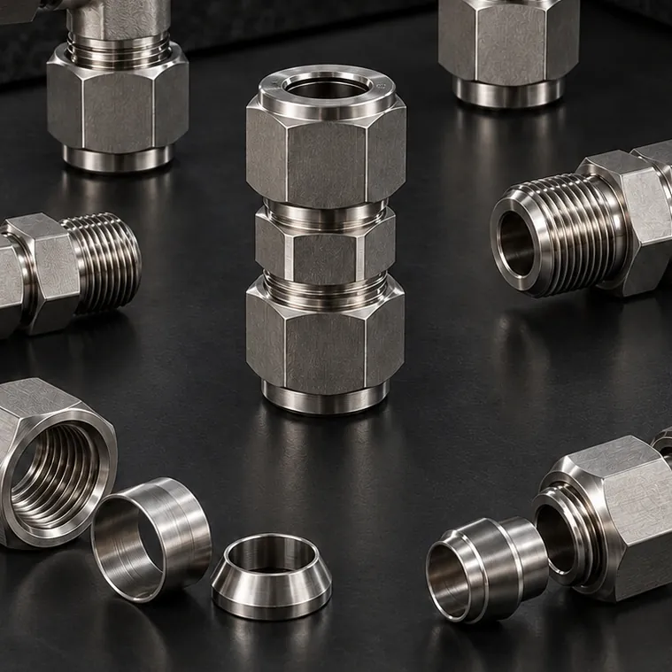 Twin Ferrule Instrumentation Fittings
 Twin Ferrule Instrumentation Fittings Twin Ferrule Instrumentation Fittings
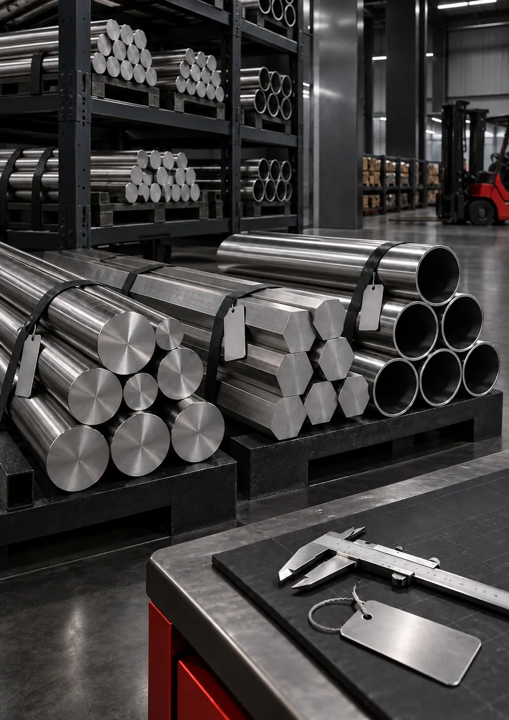 Stainless Steel Pipes & Flanges
Gallery
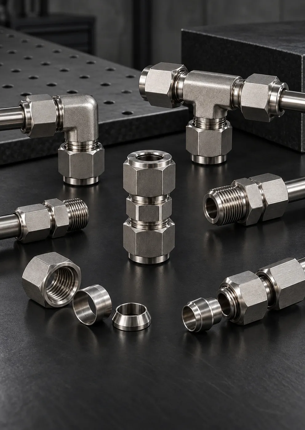
Twin-ferrule instrumentation fittings used in panel tubing (illustrative image)
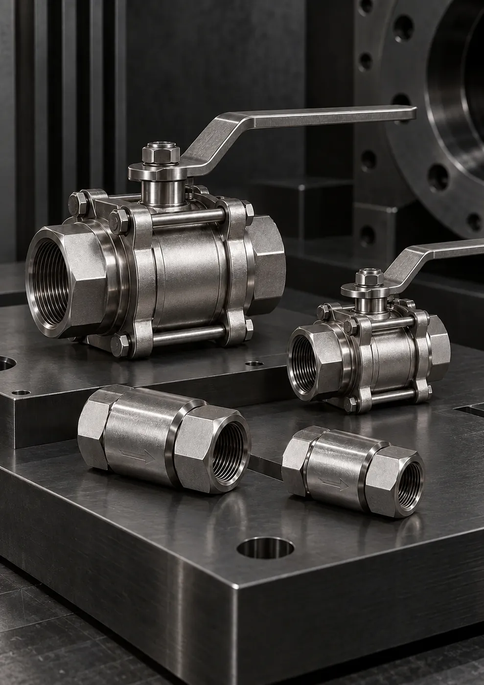
Stainless steel ball valves and check valves in panel valve groups (illustrative image)
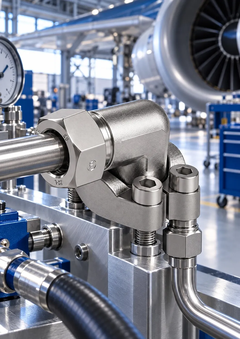 SAE flange hydraulic connection on test equipment (illustrative image)
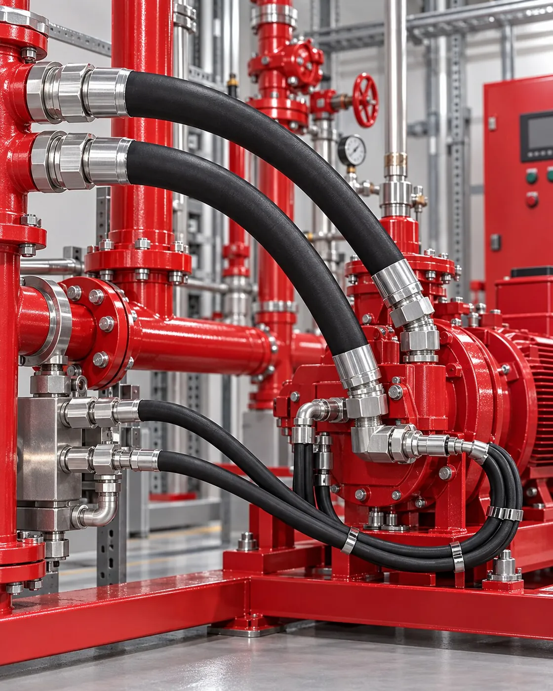 Control and connection lines on a fire pump skid (illustrative image)
FAQ
If your question isn't here, message us on WhatsApp with a ready-made message and our technical team will answer directly.
Ask on WhatsAppNo. Our scope is the stainless steel mechanical and hydraulic connection side of the panel: tubing, fittings, valves, and gauge and test point connections. Hydraulic circuit, electrical and automation design are done by the system designer; we work to the schematic provided.
A needle valve or gauge valve placed in front of the pressure gauge isolates the gauge from the system. This allows a faulty gauge, or one going out for calibration, to be replaced without shutting down the system or draining the line.
Small-bore gauge and pilot lines generally use seamless stainless steel tube and twin-ferrule instrumentation fittings, while main pressure lines use tube with a wall thickness suited to the pressure, 24° cone connections or SAE flanges. The selection is based on line pressure, diameter and maintenance needs.
The standard and sealing method are identified from a photo and the dimensions of the leaking connection. If the problem is caused by a mismatch, the correct fitting or adapter is recommended; if it is caused by a damaged surface, a new part is recommended, and if necessary the part is custom-made.
The hydraulic schematic, panel or power unit dimensions, instrument list (pressure gauges, valves, pressure switches, etc.) and connection standards. If no schematic is available, a preliminary assessment can be made from photos of the existing panel and a list of lines.
Quote and technical verification
Briefly describe your request; once size, material and lead time are clear, we'll respond with a written quote.
Details that speed up your quote