Marine & Shipping · Technical guide
Hydraulic Hose Selection, Sizing and Installation
Quick answer
The right hose assembly is defined by seven pieces of information: inside diameter and length, temperature, application conditions, fluid, working and surge pressure, the connection type at both ends, and delivery. Overall length is measured from the sealing surface of one end to the sealing surface of the other. During installation, the hose must never be bent tighter than its minimum bend radius or connected in a twisted state; these two rules directly determine service life.
The hydraulic hose is the part of the system that moves the most and wears the fastest. The service life of a hose assembly is determined by the hose type, the end fittings, the crimp quality and the way the hose is routed, all working together. When a hose ordered as "the same as the old one" turns out not to match in the field, the cause is usually missing information. In this guide we list the information needed to define the right hose assembly and the points to watch during installation.
Seven questions for selection
Hose selection commonly relies on a checklist known as STAMPED, an acronym formed from the initials of its criteria. Criterion by criterion:
| Criterion | Question to ask | Why it matters |
|---|---|---|
| Size | What should the inside diameter and length be? | Inside diameter determines flow rate and flow velocity; length determines the installation geometry |
| Temperature | What are the fluid and ambient temperatures? | Once the limit is exceeded, the inner tube and outer cover age rapidly |
| Application | Where and how will the hose operate? | Movement, vibration, abrasion and bending conditions |
| Media | What fluid will be conveyed? | The inner tube material must be compatible with the fluid |
| Pressure | What are the working and surge pressures? | An assembly is only as strong as its lowest-rated component |
| Ends | Which connection type, angle and orientation? | Thread standard and sealing type must match the mating port |
| Delivery | When, how many, and how should it be packaged? | Planning, stock and manufacturing time |
The hose itself: pressure, inside diameter, temperature and fluid
Pressure: the weakest link decides
The working pressure of a hose assembly is the lowest of the pressure ratings of the hose, the end fittings and the adapter it connects to. Hydraulic hose standards (such as EN 853, EN 856 and SAE J517) typically specify a 4:1 ratio of burst pressure to maximum working pressure. This margin is there to absorb surges and aging effects; it is not meant to be used for exceeding the working pressure. Pressure spikes caused by valve closures and load shocks can rise above the gauge reading; in systems that operate with pressure surges, the hose type should be selected for these impulse cycles.
Wire-braided hoses (such as 1SN and 2SN under EN 853) and spiral-reinforced hoses (such as 4SP and 4SH under EN 856) are designed for different pressure and impulse cycles. In heavy-impulse applications such as rolling mills and presses, spiral-reinforced hoses are frequently the preferred choice.
Flow rate and inside diameter
The inside diameter determines the flow velocity at the required flow rate. An inside diameter that is too small causes pressure loss, heat build-up and noise, and on suction lines it causes pump cavitation. Because the recommended flow velocities differ for suction, return and pressure lines, the inside diameter should be selected according to the function of the line. On many hydraulic hoses the inside diameter is expressed as a "dash" number in 1/16-inch increments: a -8 hose has a 1/2" inside diameter. When replacing a hose, go by the inside diameter and the standard printed on the hose, not by the outside diameter.
Temperature and fluid compatibility
A hose's temperature limit applies to both the fluid and the ambient temperature. In areas exposed to radiant heat, as in rolling mills, using a heat-protection sleeve and routing the hose away from hot surfaces noticeably extends its service life.
For mineral oil-based hydraulic fluids, the most common inner tube material is nitrile rubber (NBR). If water-glycol, phosphate ester-based fire-resistant fluids, biodegradable oils or chemicals are to be conveyed, inner tube compatibility must be verified separately; a standard nitrile inner tube is not suitable for phosphate esters. For chemical transfer, hoses with a PTFE inner tube are considered.
End connections: thread, cone and angle
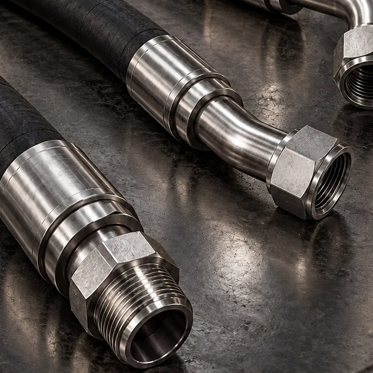
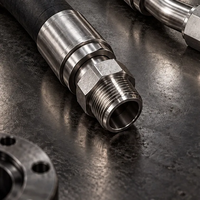
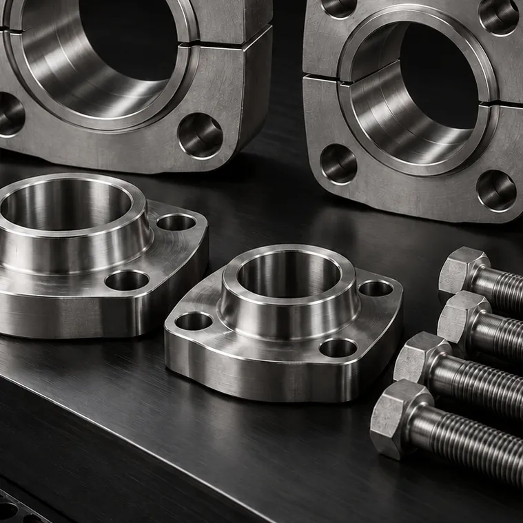
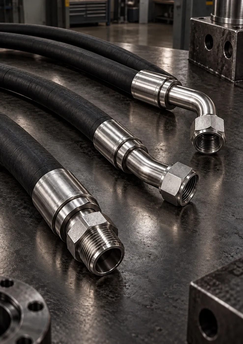
The hose end must follow the same standard as the mating port: BSP (60° cone), JIC (37° cone), ORFS (O-ring face seal), 24° cone metric or SAE flange head. In addition to the end type, its shape must also be specified: straight, 45° elbow or 90° elbow. On a hose with elbows at both ends, the angle between the ends (phase angle) is critical for installation; if the ends are crimped at the wrong angle, the hose twists as it is fitted.
Stainless steel ends deliver a long service life in applications where corrosion is the deciding factor, such as marine environments and food and chemical plants. The hose and the ends should be selected as a matched system; randomly pairing hoses and ends from different manufacturers leaves the crimp dimension uncertain.
Measuring length: the right measurement for the right order
- Overall length is measured from the sealing surface of one end to the sealing surface of the other. On ends with a female swivel nut, the reference point is not the mouth of the nut but the cone or O-ring seat inside the nut.
- On elbow ends, measure to the centerline of the sealing surface.
- If you are using the old hose as a sample, lay it out on a flat surface and measure it without stretching it; the hose may have shortened or lengthened in service.
- Describe the angle between the ends by looking along the hose from one end and stating how many degrees clockwise the other end is rotated.
This is the widely accepted measuring method. If you measured from a different point, simply state it in your order; the measuring points are confirmed together before production.
Routing: installation rules that extend service life
- Bend radius: Never go below the minimum bend radius specified by the manufacturer. Do not start the bend right where the end fitting ends; leave a straight section after the fitting.
- Twisting: The hose must not be twisted about its own axis; the layline printed on it should run straight after installation. When tightening the nut, hold the hex on the hose side with a second wrench.
- Length allowance: Under pressure, a hose can shorten or lengthen slightly. Even on straight runs, do not install the hose taut; leave a little slack.
- Movement: On moving equipment, the hose must be able to work through the full range of motion without being stretched or crushed, and the motion should take place in the hose's bending plane.
- Abrasion: Use clamps and spiral guards to keep the hose from rubbing against sharp edges, other hoses or the structure.
- Elbow adapter: In tight spaces, use a 45° or 90° adapter instead of forcing the hose into a bend; the hose becomes shorter and the bending load is eliminated.
Inspection and replacement
Replace any hose with cracking, blistering or hardening of the outer cover, exposed braid wire, or leakage or slippage at the end fitting. Never check for leaks by feeling with your hand; a jet of pressurized oil can penetrate the skin. On critical lines, record hose assemblies together with their production dates and tie them into the maintenance plan.
Checklist
- Are the inside diameter, working pressure and surge pressure known?
- Are the fluid type and temperature range known?
- Are the thread standard, sealing type and shape (straight, 45°, 90°) of both ends known?
- Has the overall length been measured, along with the phase angle for elbow ends?
- Have the bend radius, range of motion and abrasion points been checked?
- If the environment is corrosive, have stainless steel ends and, where needed, a protective sleeve been planned?
When you send a photo of the hose assembly together with this information via WhatsApp, we follow up on any missing details and define the right assembly. Hose assemblies crimped to size are prepared within an average of 5-15 business days, depending on end type, quantity and hose stock availability; hose ends and adapters in stock are ready to ship within an average of 1-3 business days.