Marine & Shipping · Technical guide
SAE Flange Code 61 vs Code 62 (SAE 3000 / 6000): Selection and Installation
Quick answer
Code 61 (ISO 6162-1) and Code 62 (ISO 6162-2) flanges are not interchangeable, even at the same nominal size: the Code 62 flange head is thicker and wider, and its bolt spacing is larger. "3000 PSI" and "6000 PSI" are series names; the working pressure must be checked in the table for each size. During installation, the O-ring is selected according to the series and the fluid, and the bolts are tightened gradually in a crisscross sequence.
SAE flange connections take the place of threaded fittings in large-diameter, high-flow hydraulic lines. They are common at pump outlets, valve blocks, cylinder feeds and power units. Whereas tightening a large-diameter threaded connection calls for oversized wrenches and plenty of swing room, a flange connection can be tightened securely with four bolts even in tight spaces and is easy to remove. However, there are two separate series, and choosing the wrong one is the most common flange mistake in the field.
Two series, two standards
SAE flanges are defined in SAE J518 and its international equivalent, ISO 6162:
- Code 61 (ISO 6162-1): Commonly referred to as the "3000 PSI series." Used in medium-pressure supply lines, return lines and large-diameter suction lines.
- Code 62 (ISO 6162-2): Referred to as the "6000 PSI series." Intended for high-pressure supply lines, presses, heavy-duty machinery and power units.
This naming is a series designation, not a working pressure that applies to every size. The allowable working pressure varies with the nominal size; in Code 61 in particular, the rating drops at larger diameters. Different editions of the standard and different manufacturers' tables may give different values. When selecting, refer to the pressure rating in the table for the relevant size, and take pressure spikes in the system into account.
Why are they not interchangeable?
At the same nominal size, Code 61 and Code 62 parts look similar at first glance, but their geometries differ:
- Bolt hole spacing: In Code 62, the distance between bolt centers is greater. A Code 61 flange does not line up with the bolt holes of a Code 62 port.
- Bolt diameter: To carry the higher load, Code 62 uses larger-diameter bolts in most sizes.
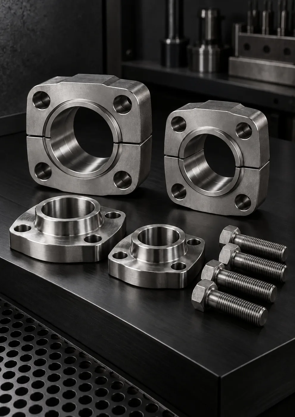
- Flange head: The Code 62 flange head is thicker and wider; split flanges are designed around this shoulder.
- Split flange and clamp: The split flange of one series does not properly grip the flange head of the other.
Even if the bolts can be forced in, the flange head does not bear evenly on the port face; the O-ring is crushed or extruded from its groove, and the connection leaks under pressure. At high pressure, this is a serious safety risk.
Identifying the series in the field
To identify the series, measure the outside diameter and thickness of the flange head and the bolt hole spacing in both directions; also check whether the bolt thread is inch (UNC) or metric. ISO 6162 covers both inch and metric bolt port options. This information is usually enough to determine the port series and the correct flange.
Comparison table
| Property | Code 61 | Code 62 |
|---|---|---|
| Standard | SAE J518 Code 61, ISO 6162-1 | SAE J518 Code 62, ISO 6162-2 |
| Common name | 3000 PSI series | 6000 PSI series |
| Working pressure | Varies by size, drops at larger diameters | Based on the table value for the relevant size |
| Bolt spacing | Narrower | Wider |
| Flange head | Thinner | Thicker and wider |
| Typical use | Supply, return and suction lines | High-pressure supply, presses and power units |
System components
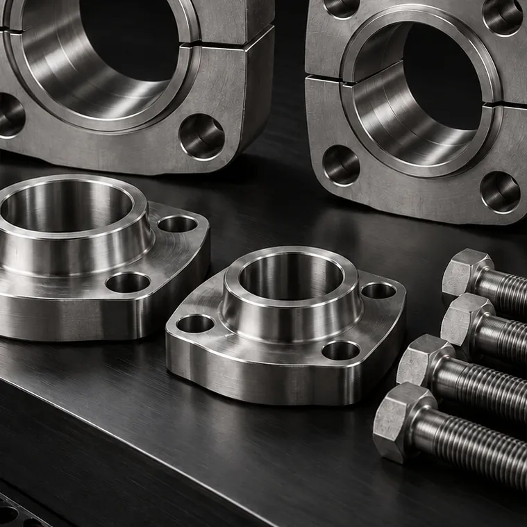
- Flange head: The shouldered end of the tube or hose end that meets the port, with an O-ring groove in its face.
- Split flange: A two-piece clamp that grips the flange head; it makes installation easier in tight spaces.
- One-piece flange: Grips the flange head with a single body; the flange must be slipped onto the tube or hose before assembly.
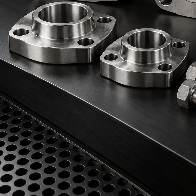
- Mating flange and flange block: Used to create a flange connection where there is no port, to change the direction of a line, or to transition to a threaded port.
O-ring: a small part with a critical job
In an SAE flange connection, the seal is made not by the metal surfaces but by the O-ring seated in the groove on the face of the flange head. Therefore:
- The O-ring size must be selected according to the series and nominal size; never use a size that merely looks "close enough."
- The material must suit the fluid and temperature: NBR is common with mineral oil, while FKM is preferred at high temperatures; compatibility with other fluids must be checked separately.
- The groove and port face must be free of scratches, burrs and paint residue.
- Before installation, the O-ring should be lightly lubricated with system fluid and placed in the groove without twisting.
- Never reuse the O-ring from a connection that has been taken apart.
Installation and crisscross tightening sequence
- Clean the port and flange head faces, and place the O-ring in the groove.
- Seat the flange head squarely against the port; fit the split flanges or the one-piece flange.
- Install all four bolts by hand, evenly. The flange should sit parallel to the port face.
- Tighten the bolts in a crisscross sequence, in several stages: first seat all the bolts at low torque, then work up gradually to the final torque.
- Take the final torque from the manufacturer's table for the bolt size and grade; do not use an estimated value.
- Once tightening is complete, check that the gap between the flange and the port is equal at all four corners.
Fully tightening one bolt before moving on to the next seats the flange at an angle; the O-ring is crushed on one side and not compressed enough on the other. This is the most common cause of installation-related flange leaks.
Using stainless steel bolts
In corrosive environments, stainless steel bolts are often specified together with a stainless steel flange head. However, the strength values of A4 stainless steel bolts differ from those of the high-strength carbon steel bolts generally called for in flange standards. Particularly in Code 62 connections, the bolt material and grade should be determined with engineering approval, taking the pressure and bolt load into account. A suitable anti-seize compound is recommended to prevent galling on stainless steel bolts.
Common flange mistakes in the field
- Bolt too long: The bolt bottoms out in the port hole; the torque wrench reaches its setting, but the flange has not been clamped firmly enough against the port. Bolt length should be selected according to the flange thickness and port thread depth.
- Mixing up inch and metric bolts: A metric bolt of similar diameter can run a few turns into a UNC-threaded port, and the port thread is permanently damaged.
- Wrong O-ring: An O-ring meant for another series or size does not seat properly in the groove; it is either crushed or not compressed enough.
- Painted or scratched surface: Paint on the flange head face or port face, and scratches made during installation, open up a leak path.
- Hose pulling on the flange: If the hose or tube attached to the flange head is not supported, its weight and vibration will loosen the connection over time.
Summary
- Code 61 and Code 62 are not interchangeable, even at the same nominal size.
- "3000 PSI" and "6000 PSI" are series names; check the working pressure for each size in the table.
- Identify the series from the bolt spacing, bolt thread, and flange head diameter and thickness.
- The O-ring size and material must suit the series and the fluid.
- Bolts must be tightened in a crisscross sequence, in stages, to the torque given in the table.
GÜNEYSS supplies AISI 316/316L SAE flange blocks, clamps, mating flanges and fittings, and manufactures non-standard blocks and transition pieces from technical drawings.