Offshore & Drilling · Technical guide
Twin Ferrule Instrumentation Fittings: Installation Guide
Quick answer
In a twin-ferrule fitting, the front ferrule provides the seal and the back ferrule grips the tube. For correct installation, the tube is cut square, deburred and pushed all the way to the bottom of the body, and the nut is tightened by the number of turns specified by the manufacturer. The most common mistake is mixing up inch and metric tubing: 1/4 inch (6.35 mm) and 6 mm tube are not interchangeable.
Twin-ferrule instrumentation fittings are used on small-bore lines such as pressure gauge lines, sampling circuits, pressure transmitters and analyzer connections. These fittings hold the tube with a controlled grip, without welding or threading. Installed correctly, they run trouble-free for a long time; but a small oversight in tube preparation can cause the fitting to leak at the first pressurization or to let go of the tube.
How does a twin-ferrule fitting work?
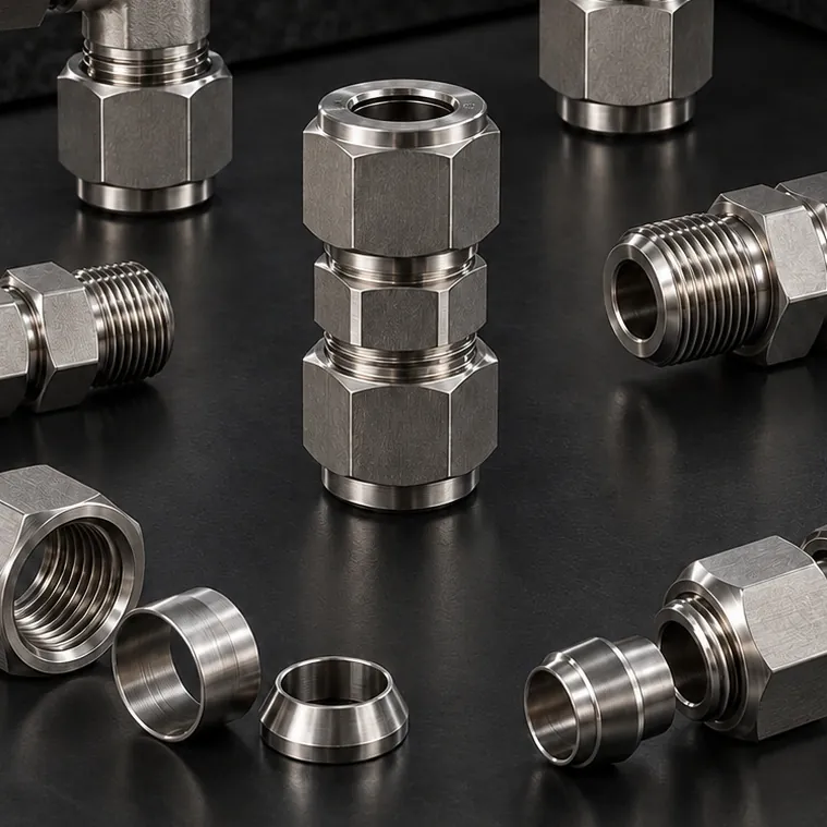
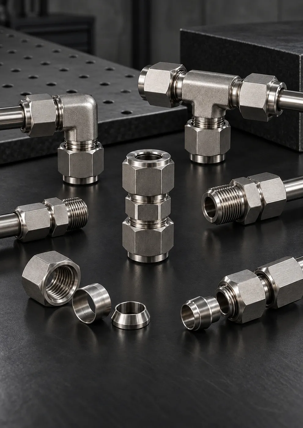
The fitting consists of four parts: body, nut, front ferrule and back ferrule. As the nut is tightened, the front ferrule is pressed into the conical seat of the body and against the tube surface, creating the seal. The back ferrule drives the front ferrule forward, grips the tube and strengthens the hold against vibration. For this mechanism to work correctly, the size, material and hardness of the tube must be compatible with the fitting.
Tube selection: watch out for size mix-ups
Instrumentation tubing is manufactured in two separate size families: inch and metric. Some sizes are very close to each other and cannot be told apart by eye:
| Metric tube | Nearest inch tube | Inch tube size in millimeters |
|---|---|---|
| 6 mm | 1/4" | 6.35 mm |
| 8 mm | 5/16" | 7.94 mm |
| 10 mm | 3/8" | 9.53 mm |
| 12 mm | 1/2" | 12.70 mm |
Installing an inch fitting on metric tube, or a metric fitting on inch tube, may go unnoticed during installation; under pressure, however, the fitting can leak or release the tube. Select tube and fittings from the same size family, keep them separate in stock and label them.
- The tube's outside diameter tolerance and wall thickness must fall within the range recommended by the fitting manufacturer.
- Stainless steel fittings require annealed 316/316L tubing with a scratch-free surface; the tube must not be harder than the ferrule.
- If the tube has longitudinal scratches, dents or ovality, that section must be cut off and discarded.
- Very thin-walled tube can collapse inward under the grip of the ferrule; wall thickness must therefore be selected together with the working pressure and in line with the fitting manufacturer's recommendation.
- Tubing of a different material must not be used with a stainless steel body; material compatibility matters for both sealing and galvanic corrosion.
Step-by-step installation
1. Cutting the tube
Cut the tube square to its axis with a tube cutter or a guided hacksaw. If you are using a tube cutter, advance the blade only slightly on each turn; pressing too hard crushes the tube end inward and makes it oval.
2. Deburring and cleaning
Remove the burrs from the inner and outer edges of the tube end with a suitable deburring tool. Chips and burrs must not get into the line; they can clog the measuring instrument or keep the ferrule from seating properly. After cutting, clean the inside of the tube with clean, dry air or another suitable method.
3. Bottoming the tube
With the nut and ferrules in place on the body, push the tube all the way in until it rests against the shoulder inside the body. If the tube is not bottomed, the ferrule grips the tube at the wrong point; the fitting may leak under pressure or the tube may slip out. Once the tube is bottomed, tighten the nut finger-tight.
4. Marking and tightening
With the nut finger-tight, draw a mark lined up across the nut and the body. Holding the body steady with a wrench, tighten the nut by the number of turns specified by the manufacturer. In many twin-ferrule systems, this is 1¼ turns past finger-tight for sizes from 1/4" to 1"; fewer turns are specified for very small diameters. Follow the installation instructions for the fitting you are using, and never guess the number of turns. The mark lets you keep track of how far you have turned the nut.
5. Inspection
If the manufacturer supplies a gap inspection gauge, insert it between the nut and the body to check whether the fitting has been tightened sufficiently. If the gauge fits into the gap, the fitting has not been tightened enough.
6. Pressurization and leak check
Once installation is complete, the line should be pressurized gradually. A suitable leak detection fluid can be applied to the fitting for the leak check; if bubbles form at a fitting, do not work on it until the line has been depressurized. Leak tolerance on gas lines is far lower than on liquid lines, so every installation step on these lines must be carried out with particular care.
Reassembly
A fitting disassembled for maintenance can be reinstalled with its ferrules still on the tube. Seat the tube together with its ferrules in the body, bring the nut back to its previous position, then apply a slight additional tightening. Going too far past the previous position crushes the ferrules and the tube. On a damaged or leaking fitting, the tube end should be cut off and the installation repeated with a new ferrule set.
Most common mistakes
- Not bottoming the tube: The most common cause of leaks and tube slippage.
- Mixing inch and metric parts: The tube, ferrules, nut and body must all belong to the same size family.
- Mixing parts from different manufacturers: Ferrule geometries can differ; the body, nut and ferrules must come from the same system.
- Overtightening: Crushes the ferrules and the tube and makes reassembly difficult.
- Applying tape or sealant on the tube side: On the twin-ferrule side, the ferrule provides the seal; tape and paste end up inside the line. Thread sealant is used only on tapered thread ends such as NPT.
- Bending too close to the fitting: A straight section of tube must be left between the bend and the fitting; otherwise the tube cannot bottom.
- Tightening a fitting under pressure: If there is a leak, depressurize the line first.
Line layout, bending and support
On instrumentation lines, the tube must be supported with clamps so that no load is transferred to the fittings; long, unsupported tube runs strain the fittings through vibration. Installing a union or a valve ahead of instruments that need maintenance allows an instrument to be replaced without dismantling the line. Unions, elbows, tees, connectors and adapters should be planned together as a group according to the line layout.
Tube bending
Bending the tube instead of putting an elbow at every change of direction reduces the number of fittings and therefore the number of potential leak points. Bending should be done with a bender whose die matches the tube outside diameter; a bend made by hand or with an unsuitable die makes the tube oval and causes wrinkling on the inside of the bend. Between bends, and between a bend and a fitting, leave enough straight length for the tube to enter the body straight. If there are several bends on the same line, measure and mark them all first, then bend.
Checklist
- Are the tube and fitting from the same size family (inch or metric)?
- Was the tube cut square and deburred inside and out?
- Is the tube seated against the shoulder in the body?
- Was the nut marked and tightened by the number of turns given in the manufacturer's instructions?
- Where available, was the fitting checked with a gap inspection gauge?
- Is the line supported with clamps?