Marine & Shipping · Technical guide
Selecting Flanges and Fittings for Stainless Steel Piping
Quick answer
On a stainless steel pipeline, fittings and flanges are selected by matching them to the pipe's DN/NPS size and Schedule wall thickness. Weld neck flanges are used on lines subject to pressure and vibration, slip-on flanges under moderate conditions and blind flanges for closing off a line; gaskets and bolts are specified according to the flange's pressure class and facing. Flanges are never forced into alignment with the bolts, and heat tint is removed after welding.
On a stainless steel pipeline, elbows, tees, reducers and flanges cannot be selected by nominal diameter alone. The pipe outside diameter, wall thickness, end preparation, pressure class, gasket face and bolt pattern all have to be compatible with one another. When one link in this chain is missing, the line either does not fit up at installation or leaks in service. In this article we have gathered the questions that come up most often in chemical, food, fire suppression and marine piping.
Pipe size: DN, NPS and Schedule
DN, NPS and the actual outside diameter
DN (nominal diameter) is a metric designation and NPS (nominal pipe size) an inch-based one; neither directly gives the actual outside diameter of the pipe. For example, in the ASME sizing system an NPS 2 (DN 50) pipe has an outside diameter of 60.3 mm. Moreover, the same DN value can correspond to different outside diameters in different pipe standards; hygienic process tubing in particular follows different outside diameter series. Specifying the pipe outside diameter and standard instead of the nominal value when ordering fittings and flanges prevents errors.
Schedule and wall thickness
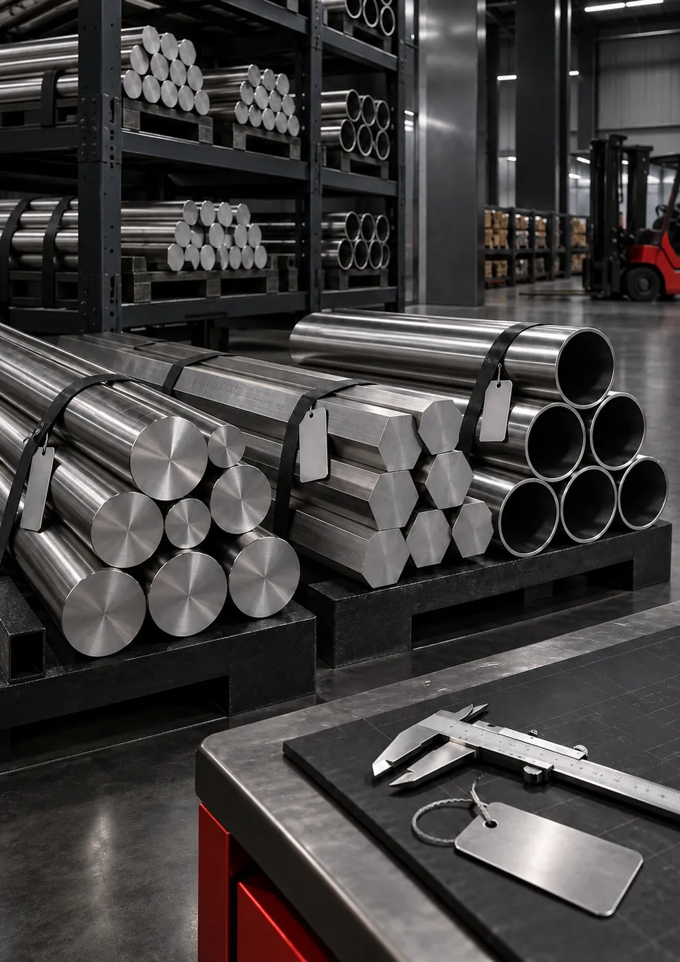
Pipes of the same nominal size are produced in different wall thicknesses. Stainless steel pipes covered by ASME B36.19M use series such as Schedule 5S, 10S, 40S and 80S. As the Schedule increases, the outside diameter stays the same, the wall thickness increases and the inside diameter decreases.
- Wall thickness is selected based on working pressure, temperature, corrosion allowance and the mechanical loads on the line.
- Butt-weld fittings must have the same Schedule wall thickness as the pipe; mismatched wall thicknesses create a step at the weld bevel.
- The bore of a weld neck flange must match the inside diameter of the pipe.
Fittings: the geometry of the line
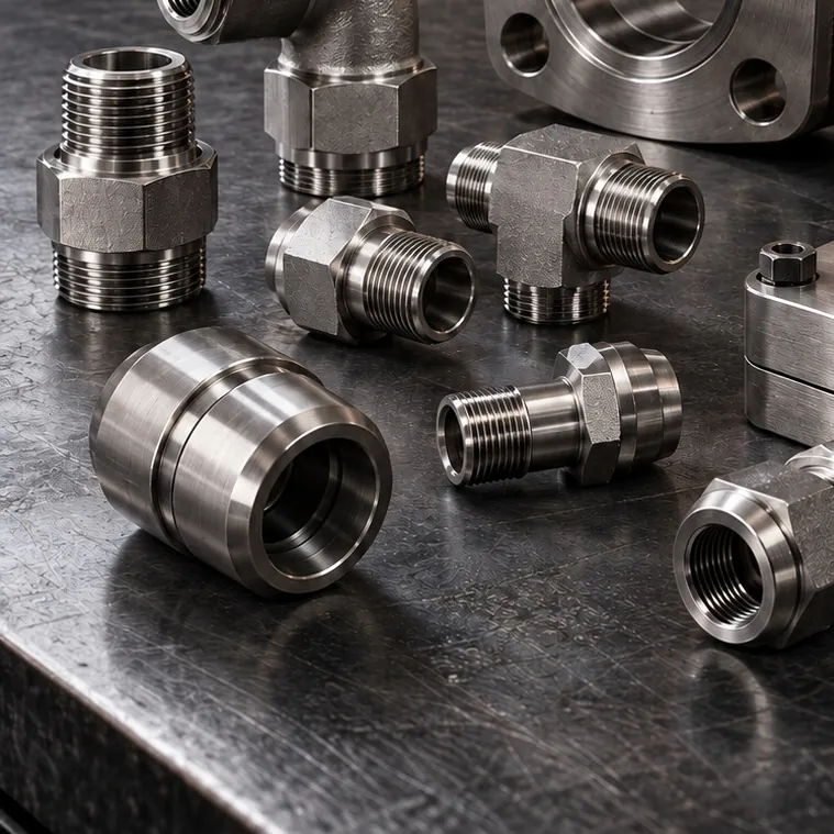
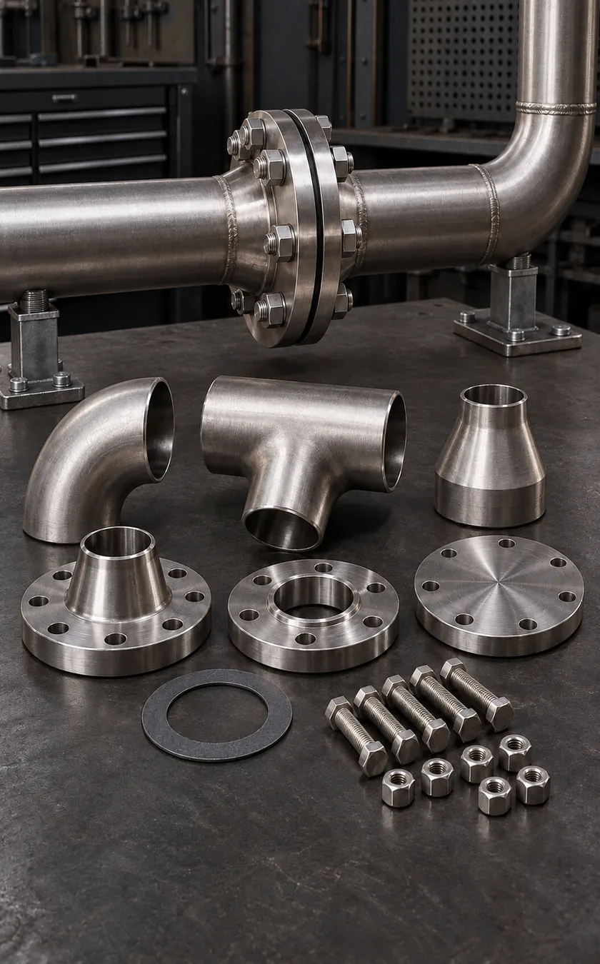
Butt-weld fittings (such as ASME B16.9) change the direction and diameter of the line:
- Elbow: 90° and 45°. Long-radius (LR, 1.5D) elbows offer less resistance to flow; short-radius (SR, 1D) elbows are used in tight spaces.
- Tee: With an equal or reducing outlet, for taking a branch off the line.
- Reducer: Concentric or eccentric. On pump suction lines, an eccentric reducer is installed with its flat side on top to prevent air pockets from forming.
- Cap: For closing off the end of a line by welding.
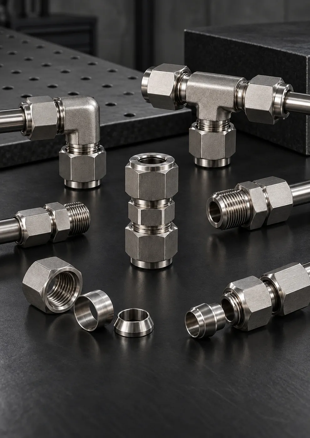
Socket-weld or threaded fittings can also be used on small-bore lines. However, the narrow gap left in socket-weld joints carries a risk of crevice corrosion in corrosive environments and creates an area that cannot be cleaned in hygienic applications.
Flange types
| Flange type | Where is it used? | Advantage | Watch out for |
|---|---|---|---|
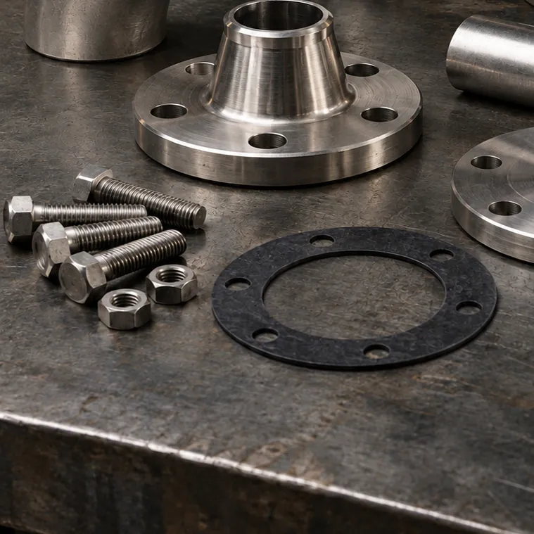
| Weld neck | High pressure and temperature, cyclic loads | The neck transfers stress gradually into the pipe; the butt weld is suitable for inspection | Neck bore must match the pipe; precise axial alignment is required |
| Slip-on | Medium- and low-pressure lines | Slides onto the pipe and is easy to align | Requires two fillet welds, inside and outside; fatigue strength is lower than that of a weld neck |
| Blind | Line ends, test points and future expansion points | Closes off the line while keeping it removable | Carries the pressure load on its own; the pressure class must match the line |
| Lap joint flange and stub end | Lines that are dismantled frequently or require bolt-hole alignment | The rotating flange makes bolt-hole alignment easier; only the stub end is in contact with the fluid | The flange ring and stub end must be selected together |
Pressure class and facing type
For ASME B16.5 flanges, the pressure class is designated as Class 150, 300, 600 and so on; for EN 1092-1 flanges, as PN 10, PN 16, PN 40 and so on. The bolt circle and hole pattern of the two systems differ in most sizes, so ASME and EN flanges must not be mixed. The flange facing must also match: raised face (RF), flat face (FF) or ring-type joint (RTJ). Bolting a raised-face flange to a flat-faced cast equipment flange can crack the cast flange during tightening.
Gaskets and bolts
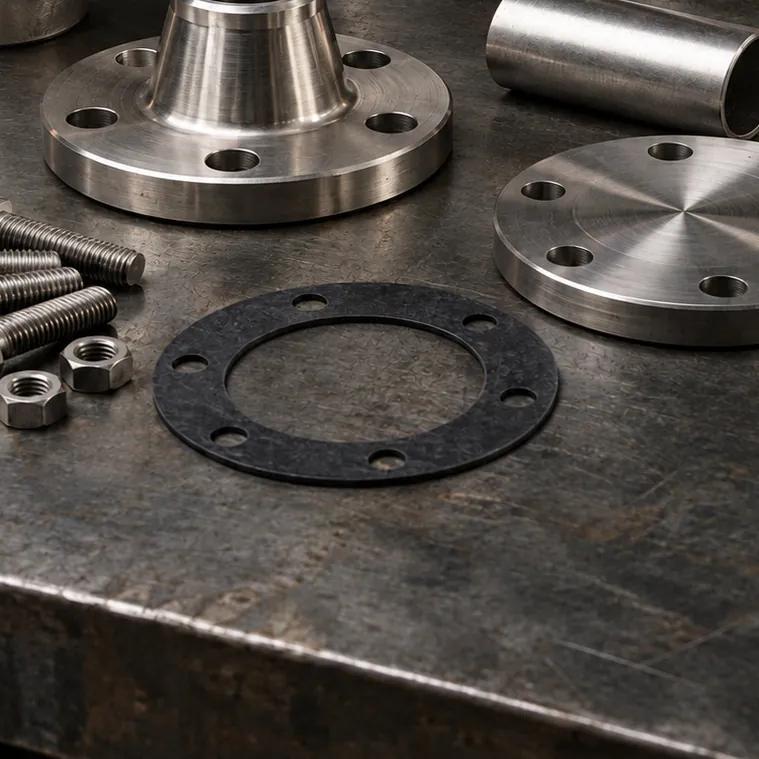
- Gasket material is selected according to the fluid and temperature: PTFE-based, graphite, compressed fiber and spiral-wound gaskets are each intended for different conditions. On food lines, a material with documented suitability for food contact must be used.
- Gasket size must be compatible with the flange's pressure class and facing type; the gasket's inside diameter must not protrude into the flow bore.
- Gaskets are never reused; a new gasket is fitted every time a flange is opened.
- Bolt and nut materials must be selected to suit the environment, and anti-seize compound should be used on stainless steel bolts to prevent galling.
- Tightening is done in a crisscross pattern and in several stages; on the final pass, the bolts are checked in sequence around the flange to confirm that the load is even.
Misalignment: do not use the bolts to align flanges
Flange faces must be parallel and concentric with each other before the bolts are fitted. Closing an angular gap or an offset by pulling the flanges together with the bolts crushes the gasket on one side and leaves it loose on the other. At pump and equipment nozzles, this forcing causes problems that can extend all the way to bearing and shaft seal failures. The line should be supported and clamped so that the flanges stay aligned on their own while the bolts are loose.
Post-weld cleaning
Weld quality starts with joint preparation. A weld bevel suited to the pipe wall thickness must be prepared, and the alignment of the parts to be joined must be checked before welding. The welding procedure and consumables are determined by the project specifications and the stainless steel grade being used; on 316L pipe, the filler metal must also be selected to suit this grade. The corrosion resistance of a stainless steel line, however, depends largely on the condition in which the surface is left after welding.
- Root-side shielding: If no shielding gas is supplied to the inside of the pipe during TIG welding, the root side oxidizes, leaving a rough surface that is prone to corrosion.
- Heat tint: The colored oxide bands around the weld indicate that the passive film has been weakened; they must be removed by pickling and passivation or by a suitable mechanical method.
- Iron contamination: Brushes and discs previously used on carbon steel start rust staining on stainless steel surfaces; tools dedicated to stainless steel work must be used.
- Internal cleaning: After installation, the line must be flushed to clear it of weld residue and swarf.
Choosing low-carbon 316L for welded joints reduces the risk of intergranular corrosion in the heat-affected zone.
Checklist
- Are the pipe outside diameter, standard and Schedule known?
- Does the wall thickness of the fittings match the pipe?
- Are the flange type, pressure class and facing type compatible with the mating flange?
- Is the gasket material suitable for the fluid and temperature?
- Have the bolt material, length and tightening sequence been determined?
- Do the flanges sit aligned with the bolts removed?
- Have root protection, heat tint removal and internal cleaning been completed after welding?